MRI Whole Spine : Protocol and Planning
Indications for Whole Spine MRI
- Infectious or inflammatory processes (eg.Spinal Cord Abscess or Spinal Osteomyelitis)
- Evaluation or monitoring of congenital malformations of the spinal cord
- Evaluation or monitoring of inflammation of the CNS or meninges
- Evaluation or monitoring of tumour of the CNS or meninges
- Nontraumatic vascular injuries of the spine
- Monitoring of previous spinal surgery
- Evaluation or monitoring of trauma
- Ankylosing spondylitis
- spinal metastasis
- Spine TB
Contraindications
- Any electrically, magnetically or mechanically activated implant (e.g. cardiac pacemaker, insulin pump biostimulator, neurostimulator, cochlear implant, and hearing aids)
- Intracranial aneurysm clips (unless made of titanium)
- Pregnancy (risk vs benefit ratio to be assessed)
- Ferromagnetic surgical clips or staples
- Metallic foreign body in the eye
- Metal shrapnel or bullet
Patient preparation for MRI Whole Spine
- A satisfactory written consent form must be taken from the patient before entering the scanner room
- Ask the patient to remove all metal object including keys, coins, wallet, any cards with magnetic strips, jewellery, hearing aid and hairpins
- Ask the patient to undress and change into a hospital gown
- Contrast injection risk and benefits must be explained to the patient before the scan
- Gadolinium should only be given to the patient if GFR is > 30
- If possible provide a chaperone for claustrophobic patients (e.g. relative or staff )
- Offer earplugs or headphones, possibly with music for extra comfort
- Explain the procedure to the patient
- Instruct the patient to keep still
- Note down the weight of the patient
Positioning for MRI Whole Spine
- Head first supine
- Position the patient in the spine and head and neck coils
- Connect the head and neck coil over the head. (The head and neck coil is used for axial C-spine imaging.)
- Give cushions under the legs for extra comfort
- Centre the laser beam localiser over the mid abdomen (3-4 inches above the iliac crest)

Recommended MRI Whole Spine Protocols and Planning
localiser thoraco lumbar spine
A three-plane T2/T1 localizer must be taken at the beginning to localize and plan the sequences. Localizers are typically less than 25 seconds and consist of T1/T2 weighted low-resolution scans.

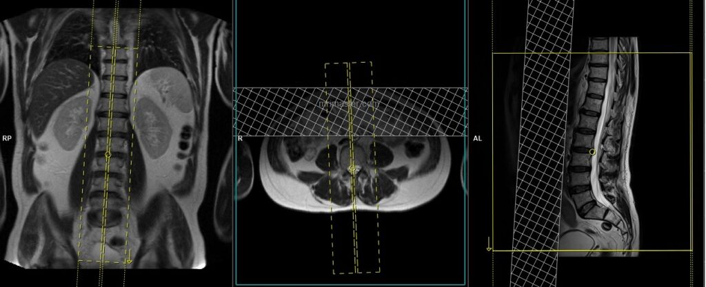
T2 tse sagittal thoraco-lumbar spine
Plan the sagittal slices on the coronal plane and angle the positioning block parallel to the thoracolumbar spine. Check the positioning block in the other two planes. An appropriate angle must be given in the axial plane, parallel to the line along the center of the vertebral body and the spinous process. Check the positioning block in the sagittal plane; the field of view (FOV) must be large enough to cover the thoracolumbar spine from T8 down to the coccyx (normally 350-400mm). The slices should be sufficient to cover the spine from the lateral border of the right (RT) transverse process up to the lateral border of the left (LT) transverse process. Place a saturation band over the abdomen in the sagittal plane, as shown in the diagram. This is done to avoid breathing artifacts over the spinal area. The phase direction should be head to feet to minimize further motion artifacts from the chest.
Parameters
TR 3000-5000 | TE 100-120 | SLICE 4MM | FLIP 130-150 | PHASE H>F | MATRIX 512X512 | FOV 350-400 | GAP 10% | NEX(AVRAGE) 2 |
T1 tse sagittal thoraco-lumbar spine
Plan the sagittal slices on the coronal plane and angle the positioning block parallel to the thoracolumbar spine. Check the positioning block in the other two planes. An appropriate angle must be given in the axial plane, parallel to the line along the center of the vertebral body and the spinous process. Check the positioning block in the sagittal plane; the field of view (FOV) must be large enough to cover the thoracolumbar spine from T8 down to the coccyx (normally 350-400mm). The slices should be sufficient to cover the spine from the lateral border of the right (RT) transverse process up to the lateral border of the left (LT) transverse process. Place a saturation band over the abdomen in the sagittal plane, as shown in the diagram. This is done to avoid breathing artifacts over the spinal area. The phase direction should be head to feet to minimize further motion artifacts from the chest.
Parameters
TR 400-600 | TE 15-25 | SLICE 4 MM | FLIP 90 | PHASE H>F | MATRIX 512X512 | FOV 350-400 | GAP 10% | NEX(AVRAGE) 2 |
T2 TSE STIR sagittal thoraco-lumbar spine
Plan the sagittal slices on the coronal plane and angle the positioning block parallel to the thoracolumbar spine. Check the positioning block in the other two planes. An appropriate angle must be given in the axial plane, parallel to the line along the center of the vertebral body and the spinous process. Check the positioning block in the sagittal plane; the field of view (FOV) must be large enough to cover the thoracolumbar spine from T8 down to the coccyx (normally 350-400mm). The slices should be sufficient to cover the spine from the lateral border of the right (RT) transverse process up to the lateral border of the left (LT) transverse process. Place a saturation band over the abdomen in the sagittal plane, as shown in the diagram. This is done to avoid breathing artifacts over the spinal area. The phase direction should be head to feet to minimize further motion artifacts from the chest.
Parameters
TR 4000-5000 | TE 110 | FLIP 130 | NEX 2 | SLICE 4MM | MATRIX 512X384 | FOV 350-400 | PHASE H>F | GAP 10% | TI 130 |
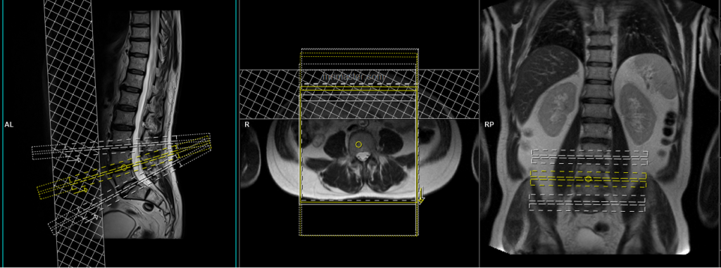
T2-TSE axial with multiple blocks and angle
Plan the axial slices on the sagittal plane, angling the first position block parallel to the L5-S1 intervertebral disc, the second position block parallel to the L4-L5 intervertebral disc, and the third position block parallel to the L3-L4 intervertebral disc (only three blocks are needed in a normal spine). Additional blocks should be taken in the presence of a prolapsed disc or cord compression at any other level. Provide an appropriate angle in the coronal plane, horizontally across the intervertebral disc space. The number of slices should be sufficient to cover the intervertebral discs (normally 5 slices for each disc space). Place a saturation band over the abdomen (in front of the aorta) on the sagittal plane to avoid peristalsis and breathing artifacts over the spinal area.
Note: If the pathology is localized to a specific part of the thoracic or lumbar spine, only perform axial scans over the affected area (e.g., for bulging discs, cord compressions, or spinal cord tumors).
Parameters
TR 3000-4000 | TE 100-120 | SLICE 3 MM | FLIP 130-150 | PHASE A>P | MATRIX 320X256 | FOV 180-200 | GAP 10% | NEX(AVRAGE) 2 |
T1 TSE axial with multiple blocks and angle
Plan the axial slices on the sagittal plane, angling the first position block parallel to the L5-S1 intervertebral disc, the second position block parallel to the L4-L5 intervertebral disc, and the third position block parallel to the L3-L4 intervertebral disc (only three blocks are needed in a normal spine). Additional blocks should be taken in the presence of a prolapsed disc or cord compression at any other level. Provide an appropriate angle in the coronal plane, horizontally across the intervertebral disc space. The number of slices should be sufficient to cover the intervertebral discs (normally 5 slices for each disc space). Place a saturation band over the abdomen (in front of the aorta) on the sagittal plane to avoid peristalsis and breathing artifacts over the spinal area.
Parameters
TR 400-600 | TE 15-25 | SLICE 3 MM | FLIP 90 | PHASE A>P | MATRIX 320X304 | FOV 180-200 | GAP 10% | NEX(AVRAGE) 2 |
localiser cervico-thoracic spine
A three-plane T2/T1 localizer must be taken at the beginning to localize and plan the sequences. Localizers are typically less than 25 seconds and consist of T1/T2 weighted low-resolution scans.

T2 TSE sagittal cervico-thoracic spine
Plan the sagittal slices on the coronal plane and angle the positioning block parallel to the cervicothoracic spine. Check the positioning block in the other two planes. An appropriate angle must be given in the axial plane, parallel to the line along the center of the vertebral body and the spinous process. Check the positioning block in the sagittal plane; the field of view (FOV) must be large enough to cover the cervicothoracic spine from 1 inch above C1 down to T10 (normally 350-400 mm). The slices should be sufficient to cover the spine from the lateral border of the right (RT) transverse process up to the lateral border of the left (LT) transverse process. Place a saturation band over the chest in the sagittal plane, as shown in the diagram. This is done to avoid breathing artifacts over the spinal area. The phase direction should be head to feet to minimize further motion artifacts from the chest

Parameters
TR 3000-4000 | TE 100-120 | SLICE 4MM | FLIP 130-150 | PHASE H>F | MATRIX 512X512 | FOV 350-400 | GAP 10% | NEX(AVRAGE) 2 |

T1 TSE sagittal cervico-thoracic spine
Plan the sagittal slices on the coronal plane and angle the positioning block parallel to the cervicothoracic spine. Check the positioning block in the other two planes. An appropriate angle must be given in the axial plane, parallel to the line along the center of the vertebral body and the spinous process. Check the positioning block in the sagittal plane; the field of view (FOV) must be large enough to cover the cervicothoracic spine from 1 inch above C1 down to T10 (normally 350-400 mm). The slices should be sufficient to cover the spine from the lateral border of the right (RT) transverse process up to the lateral border of the left (LT) transverse process. Place a saturation band over the chest in the sagittal plane, as shown in the diagram. This is done to avoid breathing artifacts over the spinal area. The phase direction should be head to feet to minimize further motion artifacts from the chest
Parameters
TR 400-600 | TE 15-25 | SLICE 4 MM | FLIP 90 | PHASE H>F | MATRIX 512X512 | FOV 350-400 | GAP 10% | NEX(AVRAGE) 2 |
T2 STIR sagittal cervico-thoracic spine
Plan the sagittal slices on the coronal plane and angle the positioning block parallel to the cervicothoracic spine. Check the positioning block in the other two planes. An appropriate angle must be given in the axial plane, parallel to the line along the center of the vertebral body and the spinous process. Check the positioning block in the sagittal plane; the field of view (FOV) must be large enough to cover the cervicothoracic spine from 1 inch above C1 down to T10 (normally 350-400 mm). The slices should be sufficient to cover the spine from the lateral border of the right (RT) transverse process up to the lateral border of the left (LT) transverse process. Place a saturation band over the chest in the sagittal plane, as shown in the diagram. This is done to avoid breathing artifacts over the spinal area. The phase direction should be head to feet to minimize further motion artifacts from the chest
Parameters
TR 4000-5000 | TE 110 | FLIP 130 | NEX 2 | SLICE 4MM | MATRIX 512X384 | FOV 350-400 | PHASE H>F | GAP 10% | TI 130 |
T2 TSE Axial block 3mm
Plan the axial slices on the sagittal plane and angle the positioning block perpendicular to the spinal cord. An appropriate angle must be given in the coronal plane, horizontally across the intervertebral disc space. The slices should be sufficient to cover the entire C spine from C1 to T1. A saturation band must be placed over the neck (in front of the esophagus) in the sagittal plane. This is done to avoid swallowing and vascular pulsation artifacts in the spinal area.
Note: If the pathology is localized to a specific part of the thoracic spine, perform axial imaging over the affected area (e.g., bulging disc, cord compressions, or spinal cord tumors)

Parameters
TR 3000-4000 | TE 100-120 | SLICE 3 MM | FLIP 130-150 | PHASE A>P | MATRIX 320X256 | FOV 160-200 | GAP 10% | NEX(AVRAGE) 2 |
T1 TSE Axial block 3mm
Plan the axial slices on the sagittal plane and angle the positioning block perpendicular to the spinal cord. An appropriate angle must be given in the coronal plane, horizontally across the intervertebral disc space. The slices should be sufficient to cover the entire C spine from C1 to T1. A saturation band must be placed over the neck (in front of the esophagus) in the sagittal plane. This is done to avoid swallowing and vascular pulsation artifacts in the spinal area.
Parameters
TR 400-600 | TE 15-25 | SLICE 3 MM | FLIP 90 | PHASE A>P | MATRIX 320X256 | FOV 160-200 | GAP 10% | NEX(AVRAGE) 2 |
Indications for contrast enhancement spine scans
- Evaluation or monitoring of tumour of the CNS or meninges
- Monitoring of previous spinal surgery
- MS, hemipeligia/paresthesia and Infection
- Suspected spine lesions (e.g. bone Mets)
- Spinal Cord Tumour
- Syringomyelia
Use T1 TSE Use T1 TSE Fat-saturated axial and sagittal sequences after the administration of intravenous gadolinium DTPA injection (following the planning outlined above). The document below provides access to the recommended dosage of gadolinium DTPA injection, as advised by the manufacturer.
Optional Scans
Planning axial blocks in cases of pathologies such as metastatic cord compression, spinal TB, or discitis
T2 TSE Axial block 3mm pathology
Plan the axial slices on the sagittal plane and angle the positioning block perpendicular to the spine. An appropriate angle must be given in the coronal plane, horizontally across the intervertebral disc space. The slices should be sufficient to cover the entire pathology. A saturation band must be placed in front of the spine in the sagittal plane. This is done to avoid swallowing and vascular pulsation artifacts in the spinal area.

TR 3000-4000 | TE 100-120 | SLICE 3 MM | FLIP 130-150 | PHASE A>P | MATRIX 320X256 | FOV 160-200 | GAP 10% | NEX(AVRAGE) 2 |
CLICK THE SEQUENCES BELOW TO CHECK THE SCANS
- LOCALIZER_3 PLANE1