MRI Orbits : Protocol and Planning
Indications for MRI Orbits scan
- Visual loss that is clinically compatible with an intracranial pre- or postchiasmal lesion
- Vascular lesions of the orbit (AV malformation , carotid-cavernous fistula, orbital varix)
- History of visual disturbances
- Optic nerve sheath meningioma
- Tumours or suspected tumours
- Thyroid ophtalmopathy
- Extraocular myopathy
- Optic nerve neuritis
- Optic nerve glioma
- Unilateral proptosis
- Orbital abscess
- Inflammation
Contraindications
- Any electrically, magnetically or mechanically activated implant (e.g. cardiac pacemaker, insulin pump biostimulator, neurostimulator, cochlear implant, and hearing aids)
- Intracranial aneurysm clips (unless made of titanium)
- Pregnancy (risk vs benefit ratio to be assessed)
- Ferromagnetic surgical clips or staples
- Metallic foreign body in the eye
- Metal shrapnel or bullet
Patient preparation for MRI Orbits scan
- A satisfactory written consent form must be taken from the patient before entering the scanner room (For paediatric patients this must be done by the parents)
- Ask the patient to remove all metal objects including keys, coins, wallet, cards with magnetic strips, jewellery, hearing aid and hairpins
- If possible provide a chaperone for claustrophobic patients (e.g. relative or staff )
- Contrast injection risk and benefits must be explained to the before the scan
- Gadolinium should only be given to the patient if GFR is > 30
- Offer earplugs or headphones, possibly with music for extra comfort
- Explain the procedure to the patient
- Instruct the patient to keep still
- Note the weight of the patient
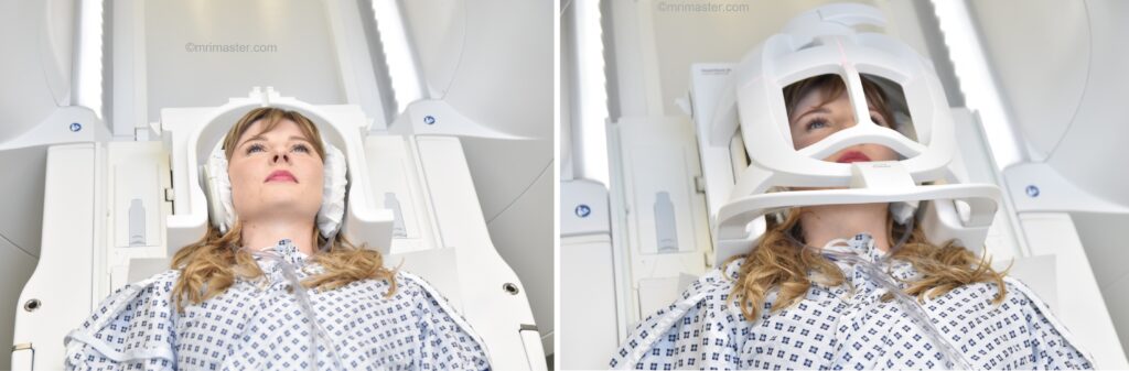
Positioning for MRI Orbits scan
- Head first supine
- Position the head in the head coil and immobilise with cushions
- Give cushions under the legs for extra comfort
- Centre the laser beam localiser over the glabella
Recommended MRI Orbits Protocols, Parameters, and Planning
localiser 1
A three plane localiser must be taken in the beginning to localise and plan the sequences. Localisers are normally less than 25sec. T1 weighted low resolution scans.

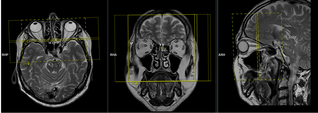
localiser 2
Plan a second T2 three-plane localizer on the first localizer. Plan the sagittal localizer on the axial image and make it parallel to the optic nerve. Plan the coronal localizer perpendicular to the right and left optic nerve, as shown in the image. Finally, plan the axial localizer in the coronal image and make it parallel to the right and left optic nerve.

T2 tse axial
Plan the axial slices on the sagittal plane and position the block parallel to the genu and splenium of the corpus callosum. Verify the planning block in the other two planes and ensure that an appropriate angle is maintained in the coronal plane, making it perpendicular to the line of the midline of the brain and the 4th ventricle. Ensure that the number of slices is sufficient to cover the entire brain from the vertex to the line of the foramen magnum.

Parameters
TR 3000-4000 | TE 100-120 | SLICE 5MM | FLIP 130-150 | PHASE R>L | MATRIX 320X320 | FOV 210-230 | GAP 10% | NEX(AVRAGE) 2 |
T2 stir coronal 3mm
Plan the coronal slices on the axial plane and angle the planning block parallel to the right (RT) and left (LT) optic nerve. Check the planning block in the other two planes. An appropriate angle must be given in the sagittal plane (perpendicular to the optic nerve). Ensure that the slices are sufficient to cover the entire orbits from the eye lenses to the optic chiasm.”
Parameters
TR 4000-5000 | TE 110 | FLIP 160 | NEX 3 | SLICE 3MM | MATRIX 256×256 | FOV 150-170 | PHASE R>L | GAP 10% | TI 150 |
T1 TSE coronal 3mm
Plan the coronal slices on the axial plane and angle the planning block parallel to the right (RT) and left (LT) optic nerve. Check the planning block in the other two planes. An appropriate angle must be given in the sagittal plane (perpendicular to the optic nerve). Ensure that the slices are sufficient to cover the entire orbits from the eye lenses to the optic chiasm.”
Parameters
TR 400-600 | TE 15-25 | SLICE 3MM | FLIP 150 | PHASE R>L | MATRIX 256X256 | FOV 150×170 | GAP 10% | NEX(AVRAGE) 3 |
T2 stir axial
Plan the axial slices on the coronal plane and angle the planning block parallel to the right (RT) and left (LT) optic nerve. Check the planning block in the other two planes. Provide an appropriate angle in the sagittal plane (parallel to the optic nerve). Ensure that the slices are sufficient to cover the entire orbits from the superior border to the inferior border.

Parameters
TR 4000-5000 | TE 110 | FLIP 160 | NEX 3 | SLICE 3MM | MATRIX 256×256 | FOV 150-170 | PHASE R>L | GAP 10% | TI 150 |
RESOLVE DWI 2trace axial
Plan the axial slices on the coronal plane and angle the planning block parallel to the right (RT) and left (LT) optic nerve. Check the planning block in the other two planes. Provide an appropriate angle in the sagittal plane (parallel to the optic nerve). Ensure that the slices are sufficient to cover the entire orbits from the superior border to the inferior border.
Parameters
TR 4000-6000 | TE 68 | FLIP 180 | NXA 1 2 | SLICE 3MM | MATRIX 192X192 | FOV 180-200 | PHASE R>L | GAP 10% | B VALUE 50 |
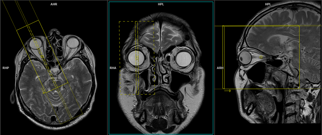
T2 tse sagittal oblique RT
Plan the sagittal slices on the axial plane and angle the planning block parallel to the optic nerve. Check the planning block in the other two planes. An appropriate angle must be given in the coronal plane, parallel to the line along the right (RT) superior and RT inferior rectus muscles. Ensure that the slices are sufficient to cover the right (RT) orbit.
Parameters
TR 3000-4000 | TE 100-120 | SLICE 3 MM | FLIP 130-150 | PHASE A>P | MATRIX 256X256 | FOV 150-170 | GAP 10% | NEX(AVRAGE) 3 |
T2 tse sagittal oblique LT
Plan the sagittal slices on the axial plane and angle the planning block parallel to the optic nerve. Check the planning block in the other two planes. An appropriate angle must be given in the coronal plane, parallel to the line along the left (LT) superior and LT inferior rectus muscles. Ensure that the slices are sufficient to cover the LT orbit.

Parameters
TR 3000-4000 | TE 100-120 | SLICE 3 MM | FLIP 130-150 | PHASE A>P | MATRIX 256X256 | FOV 150-170 | GAP 10% | NEX(AVRAGE) 3 |
For contrast enhanced scans
Post-contrast scanning will only be performed if any pathology is observed in the pre-contrast scans