MRI Pediatric Whole Spine : Protocol and Planning
Indications
- Infectious or inflammatory processes (eg.Spinal Cord Abscess or Spinal Osteomyelitis)
- Evaluation or monitoring of congenital malformations of the spinal cord
- Evaluation or monitoring of inflammation of the CNS or meninges
- Evaluation or monitoring of tumour of the CNS or meninges
- Nontraumatic vascular injuries of the spine
- Monitoring of previous spinal surgery
- Evaluation or monitoring of trauma
- Spine TB
Contraindications
- Any electrically, magnetically or mechanically activated implant (e.g. cardiac pacemaker, insulin pump biostimulator, neurostimulator, cochlear implant, and hearing aids)
- Intracranial aneurysm clips (unless made of titanium)
- Ferromagnetic surgical clips or staples
- Metallic foreign body in the eye
- Metal shrapnel or bullet
Patient preparation
- A satisfactory written consent form must be taken from the patient before entering the scanner room (For paediatric patients this must be done by the parents)
- Ask the patient to remove all metal object including keys, coins, wallet, any cards with magnetic strips, jewellery, hearing aid and hairpins
- Ask the patient to undress and change into a hospital gown
- Contrast injection risk and benefits must be explained to the patient before the scan
- Gadolinium should only be given to the patient if GFR is > 30
- If possible provide a chaperone for pediatric patients (e.g. relative or staff )
- Offer earplugs or headphones, possibly with music for extra comfort
- Explain the procedure to the patient
- Instruct the patient to keep still
- Note down the hight and weight of the patient
Patient preparation for under 3 and neonates
- Please do necessary arrangements for sedation if prescribed (oral chloral hydrate used for this purpose)
- Infants must be Fed immediately before the scan and wrap them in a warm blanket (must be done by a trained nurse).
- Room temperature must be maintained (23-24 degrees for term born infants and approx. 28 degrees for preterm infants)
- Change nappies immediately before the procedure
- If available use the acoustic noise reduction sequences
- All the ECG electrodes must be removed prior to procedure
- Sedated patients must be monitor (using MRI compactable pulse oximeter)
Positioning
- Head first supine
- Position the patient in the spine and head and neck coils
- Connect the head and neck coil over the head. (The head and neck coil is used for axial C-spine imaging.)
- Give cushions under the legs for extra comfort
- Centre the laser beam localiser over the mid abdomen (2-3 inches above the iliac crest)

Recommended MRI Pediatric Whole Spine Protocols and Planning
localiser whole spine automatic composing
The auto-composing localizer system comprises two distinct localizers, one for the thoracolumbar spine and another for the cervicothoracic spine. After completing the localizer for the thoracolumbar spine, the table will automatically reposition itself and perform a cervical thoracic localizer. Once both localizers are finished, the system will merge them together to generate a coronal and sagittal localizer for the entire spine.

T2 TSE sagittal 2.5 mm whole spine automatic composing
When utilizing the auto-composing protocol, the whole spine auto-compose localizer will display both the cervicothoracic and thoracolumbar blocks. The planning process should commence with the cervicothoracic block, ensuring its complete configuration before moving on to the thoracolumbar block. It is essential to have adequate overlap between the blocks. Once both blocks are planned and appropriately positioned, the user can initiate the scan. Subsequently, the system will automatically combine the blocks and generate sagittal images of the entire spine.
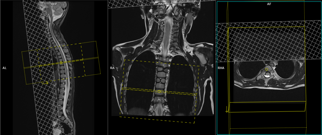
For the cervicothoracic planning block, it should be planned on the coronal plane, with the positioning block aligned parallel to the cervicothoracic spine. Verification of the positioning block is necessary in the axial and sagittal planes. In the axial plane, the angle should parallel the line connecting the center of the vertebral body and the spinous process. In the sagittal plane, the field of view (FOV) should cover the cervicothoracic spine from 1 inch above C1 to T11, typically ranging from 200-250 mm. The slices should adequately encompass the spine from the lateral border of the right transverse process to the lateral border of the left transverse process. To minimize breathing artifacts over the spinal area, a saturation band should be positioned over the chest in the sagittal plane, as illustrated in the diagram. The phase direction should be from head to feet to minimize motion artifacts originating from the chest.
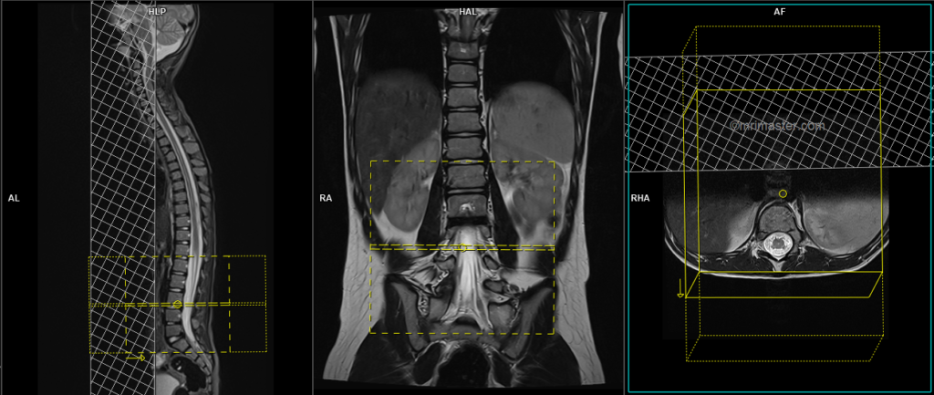
Likewise, for the thoracolumbar planning block, it should be planned on the coronal plane, with the positioning block angled parallel to the thoracolumbar spine. Verification of the positioning block is necessary in the axial and sagittal planes, ensuring an appropriate angle parallel to the line connecting the center of the vertebral body and the spinous process in the axial plane. The sagittal plane FOV should cover the thoracolumbar spine from T7 to the coccyx, typically ranging from 200-250 mm. The slices should adequately encompass the spine from the lateral border of the right transverse process to the lateral border of the left transverse process. To prevent breathing artifacts, a saturation band should be positioned over the abdomen in the sagittal plane, as depicted in the diagram. The phase direction should be from head to feet to minimize motion artifacts originating from the chest.

Parameters
TR 3000-5000 | TE 100-120 | SLICE 2.5MM | FLIP 130-150 | PHASE H>F | MATRIX 304X304 | FOV 200-250 | GAP 10% | NEX(AVRAGE) 2 |
When conducting spine imaging in children, it is crucial to conduct scans with a small field of view (FOV) and thinner slices (e.g., 250mm FOV with 2 to 3mm slice thickness). Another important aspect to consider is the duration of each sequence. The sagittal acquisition time should range from 1 to 2 minutes. Please modify the scanner parameters to achieve faster scans, although this may not be feasible on older generation scanners.
T1 tse sagittal 2.5mm whole spine automatic composing
For the cervicothoracic planning block, it should be planned on the coronal plane, with the positioning block aligned parallel to the cervicothoracic spine. Verification of the positioning block is necessary in the axial and sagittal planes. In the axial plane, the angle should parallel the line connecting the center of the vertebral body and the spinous process. In the sagittal plane, the field of view (FOV) should cover the cervicothoracic spine from 1 inch above C1 to T11, typically ranging from 200-250 mm. The slices should adequately encompass the spine from the lateral border of the right transverse process to the lateral border of the left transverse process. To minimize breathing artifacts over the spinal area, a saturation band should be positioned over the chest in the sagittal plane, as illustrated in the diagram. The phase direction should be from head to feet to minimize motion artifacts originating from the chest.
Likewise, for the thoracolumbar planning block, it should be planned on the coronal plane, with the positioning block angled parallel to the thoracolumbar spine. Verification of the positioning block is necessary in the axial and sagittal planes, ensuring an appropriate angle parallel to the line connecting the center of the vertebral body and the spinous process in the axial plane. The sagittal plane FOV should cover the thoracolumbar spine from T7 to the coccyx, typically ranging from 200-250 mm. The slices should adequately encompass the spine from the lateral border of the right transverse process to the lateral border of the left transverse process. To prevent breathing artifacts, a saturation band should be positioned over the abdomen in the sagittal plane, as depicted in the diagram. The phase direction should be from head to feet to minimize motion artifacts originating from the chest.
Parameters
TR 400-600 | TE 15-25 | SLICE 2.5 MM | FLIP 90 | PHASE H>F | MATRIX 304X304 | FOV 350-400 | GAP 10% | NEX(AVRAGE) 2 |
T2 STIR sagittal 2.5mm whole spine automatic composing
For the cervicothoracic planning block, it should be planned on the coronal plane, with the positioning block aligned parallel to the cervicothoracic spine. Verification of the positioning block is necessary in the axial and sagittal planes. In the axial plane, the angle should parallel the line connecting the center of the vertebral body and the spinous process. In the sagittal plane, the field of view (FOV) should cover the cervicothoracic spine from 1 inch above C1 to T11, typically ranging from 200-250 mm. The slices should adequately encompass the spine from the lateral border of the right transverse process to the lateral border of the left transverse process. To minimize breathing artifacts over the spinal area, a saturation band should be positioned over the chest in the sagittal plane, as illustrated in the diagram. The phase direction should be from head to feet to minimize motion artifacts originating from the chest.
Likewise, for the thoracolumbar planning block, it should be planned on the coronal plane, with the positioning block angled parallel to the thoracolumbar spine. Verification of the positioning block is necessary in the axial and sagittal planes, ensuring an appropriate angle parallel to the line connecting the center of the vertebral body and the spinous process in the axial plane. The sagittal plane FOV should cover the thoracolumbar spine from T7 to the coccyx, typically ranging from 200-250 mm. The slices should adequately encompass the spine from the lateral border of the right transverse process to the lateral border of the left transverse process. To prevent breathing artifacts, a saturation band should be positioned over the abdomen in the sagittal plane, as depicted in the diagram. The phase direction should be from head to feet to minimize motion artifacts originating from the chest.
Parameters
TR 4000-5000 | TE 110 | FLIP 130 | NEX 2 | SLICE 2.5MM | MATRIX 256X256 | FOV 200-250 | PHASE H>F | GAP 10% | TI 150 |
T2-TSE axial block 3mm SFOV lumbar spine
Whole spine scans are commonly performed for various purposes, such as trauma, tuberculosis (TB) spine evaluation, spinal cord tumors, and spine infections. In these cases, it is preferable to conduct an axial block specifically targeting the affected pathology, rather than relying on disc axials. However, if no pathology is identified, it is recommended to perform axial blocks covering both the lumbar and cervical areas.
To plan the axial block, position the block perpendicularly to the lumbar spine on the sagittal plane. The positioning block should be checked in the other two planes as well. Ensure an appropriate angle horizontally across the intervertebral disc space in the coronal plane. The number of slices should be sufficient to cover the pathology adequately. Additionally, place a saturation band over the abdomen, specifically in front of the aorta, on the sagittal plane. This helps to minimize artifacts caused by peristalsis and breathing, particularly over the spinal area.
Note: If spina bifida is suspected, the axial block should cover the lower lumbar and full sacrum.
Parameters
TR 3000-4000 | TE 100-120 | SLICE 3MM | FLIP 130-150 | PHASE A>P | MATRIX 256X256 | FOV 140-160 | GAP 10% | NEX(AVRAGE) 2 |
T1 TSE axial axial block 3mm SFOV lumbar spine
Plan the axial block and position it perpendicular to the lumbar spine on the sagittal plane. The positioning block should also be checked in the other two planes. Ensure an appropriate angle horizontally across the intervertebral disc space in the coronal plane. The number of slices should be sufficient to adequately cover the pathology. Additionally, place a saturation band over the abdomen, specifically in front of the aorta, on the sagittal plane. This helps minimize artifacts caused by peristalsis and breathing, particularly in the spinal area.
Parameters
TR 400-600 | TE 15-25 | SLICE 3MM | FLIP 90 | PHASE A>P | MATRIX 256X224 | FOV 140-160 | GAP 10% | NEX(AVRAGE) 2 |
T2 TSE Axial block 3mm SFOV cervical spine
Plan the axial block on the sagittal plane and position the positioning block perpendicular to the cervical spine. Ensure to check the planning block in the other two planes for accurate alignment. In the coronal plane, establish an appropriate angle horizontally across the intervertebral disc space. The number of slices should be adequate to cover the pathology under evaluation. To mitigate the impact of swallowing and vascular pulsation artifacts in the spinal area, place a saturation band over the neck in the sagittal plane, specifically in front of the esophagus.

Parameters
TR 4000-5000 | TE 100-120 | SLICE 3MM | FLIP 130-150 | PHASE A>P | MATRIX 256X256 | FOV 140-160 | GAP 10% | NEX(AVRAGE) 2 |
T1 TSE Axial block 3mm SFOV cervical spine
Plan the axial block on the sagittal plane and position the positioning block perpendicular to the cervical spine. Ensure to check the planning block in the other two planes for accurate alignment. In the coronal plane, establish an appropriate angle horizontally across the intervertebral disc space. The number of slices should be adequate to cover the pathology under evaluation. To mitigate the impact of swallowing and vascular pulsation artifacts in the spinal area, place a saturation band over the neck in the sagittal plane, specifically in front of the esophagus.
Parameters
TR 400-600 | TE 15-25 | SLICE 3MM | FLIP 90 | PHASE A>P | MATRIX 256X256 | FOV 140-160 | GAP 10% | NEX(AVRAGE) 2 |
T2 TSE Axial block 3mm SFOV thoracic spine
Plan the axial block using the sagittal plane as a reference and position the positioning block perpendicular to the thoracic spine. It is important to check the planning block’s alignment in the other two planes to ensure accuracy. In the coronal plane, establish the appropriate angle horizontally across the intervertebral disc space. The number of slices should be sufficient to cover the pathology being evaluated. To minimize the impact of artifacts caused by swallowing and vascular pulsations in the spinal area, place a saturation band over the chest in the sagittal plane in front of the thoracic vertebral bodies.
Parameters
TR 4000-6000 | TE 100-120 | SLICE 3MM | FLIP 130-150 | PHASE A>P | MATRIX 256X224 | FOV 140-160 | GAP 10% | NEX(AVRAGE) 2 |
T1 TSE Axial block 3mm SFOV thoracic spine
Plan the axial block using the sagittal plane as a reference and position the positioning block perpendicular to the thoracic spine. It is important to check the planning block’s alignment in the other two planes to ensure accuracy. In the coronal plane, establish the appropriate angle horizontally across the intervertebral disc space. The number of slices should be sufficient to cover the pathology being evaluated. To minimize the impact of artifacts caused by swallowing and vascular pulsations in the spinal area, place a saturation band over the chest in the sagittal plane in front of the thoracic vertebral bodies.
Parameters
TR 450-700 | TE 15-25 | SLICE 3MM | FLIP 90 | PHASE A>P | MATRIX 256X224 | FOV 140-160 | GAP 10% | NEX(AVRAGE) 2 |
Indications for contrast enhancement spine scans
- Evaluation or monitoring of tumour of the CNS or meninges
- Monitoring of previous spinal surgery
- MS, hemipeligia/paresthesia and Infection
- Suspected spine lesions (e.g. bone Mets)
- Spinal Cord Tumour
- Syringomyelia
Use T1 TSE Use T1 TSE Fat-saturated axial and sagittal sequences after the administration of intravenous gadolinium DTPA injection (following the planning outlined above). The document below provides access to the recommended dosage of gadolinium DTPA injection, as advised by the manufacturer.
CLICK THE SEQUENCES BELOW TO CHECK THE SCANS
- LOCALIZER_3 PLANE1