MRI Sialography
Introduction
MR sialography is an MRI technique utilized for evaluating salivary duct diseases in a non-invasive manner. The principle behind MR sialography relies on the fact that stationary fluids will produce a bright signal on heavily T2-weighted images. To achieve this, T2-weighted sequences with extended TR (8000), TE (500), and spectral pre-saturation inversion recovery (SPIR) fat suppression are employed to enhance fluid visibility while suppressing signals from surrounding tissues. One of the key advantages of MR sialography is its ability to not only detect sialolithiasis and changes in the ductal structure but also depict the glandular parenchyma. Additionally, MRI imaging has the potential to offer spatial information concerning salivary gland function.
Ductal Anatomy
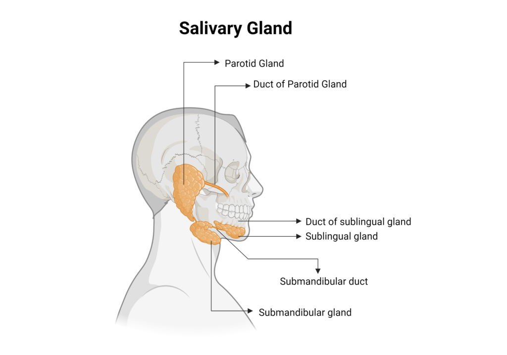
Salivary glands are a crucial component of the human digestive system, responsible for producing and secreting saliva into the oral cavity. Saliva serves various important functions, including lubrication of food, initiation of the digestive process, protection of the oral mucosa, and antimicrobial activity. The anatomy of the salivary glands is complex and comprises three major pairs of glands: the parotid glands, submandibular glands, and sublingual glands.
Parotid Glands: The parotid glands are the largest salivary glands, situated below the external acoustic meatus, between the mandible and the sternocleidomastoid muscle. The parotid duct extends from the parotid glands and runs a short distance obliquely forward between the buccinator and the oral mucosa to open upon a small papilla opposite the crown of the second upper molar. This duct is approximately 5-6 cm long and about 1-2 mm thick.
Submandibular glands: The submandibular glands are situated beneath the lower jaws, superior to the digastric muscles. The submandibular duct extends from the submandibular gland to the posterior edge of the mylohyoid muscle, curves around the muscle, then enters the sublingual space on the surface of the mylohyoid muscle, and opens into the floor of the mouth at the summit of the sublingual papilla, located at the side of the frenulum of the tongue. This duct is approximately 5cm long and about 1–3mm thick.
Sublingual glands: The sublingual glands are located beneath the tongue, just above the mylohyoid muscle. These are the smallest of the major salivary glands and consist of multiple small ducts that open into the floor of the mouth.
MRI Sialograms are only possible in the parotid and submandibular ducts.
Indications for MRI sialogram
- Identify Sialolithiasis (parotid or submandibular gland stones)
- Detect fistulae, strictures, diverticula, and cysts
- Investigate radiation induced xerostomia
- Ductal stenosis
- Inflammatory conditions
- Sjogren's syndrome
- Tumor or neoplasm
- Facial trauma
Contraindications
- Any electrically, magnetically or mechanically activated implant (e.g. cardiac pacemaker, insulin pump biostimulator, neurostimulator, cochlear implant, and hearing aids)
- Intracranial aneurysm clips (unless made of titanium)
- Pregnancy (risk vs benefit ratio to be assessed)
- Ferromagnetic surgical clips or staples
- Metallic foreign body in the eye
- Metal shrapnel or bullet
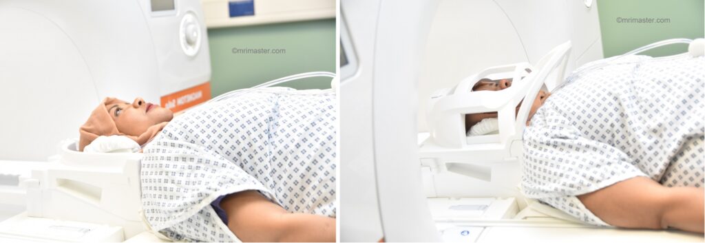
Patient preparation for MRI Sialogram
- A satisfactory written consent form must be taken from the patient before entering the scanner room
- Ask the patient to remove all metal objects including keys, coins, wallet, cards with magnetic strips, jewellery, hearing aid and hairpins
- Instruct the patient to breathe quietly and refrain from coughing or vigorous swallowing during image acquisition
- If possible provide a chaperone for claustrophobic patients (e.g. relative or staff )
- Offer earplugs or headphones, possibly with music for extra comfort
- Explain the procedure to the patient
- Instruct the patient to keep still
- Note the weight of the patient
Positioning for MRI Sialogram
- Head first supine
- Position the head in the head coil and immobilise with cushions
- Give cushions under the legs for extra comfort
- Centre the laser beam localiser over the nose tip
Parotid Sialogram
Recommended Parotid Sialogram Protocols and Planning
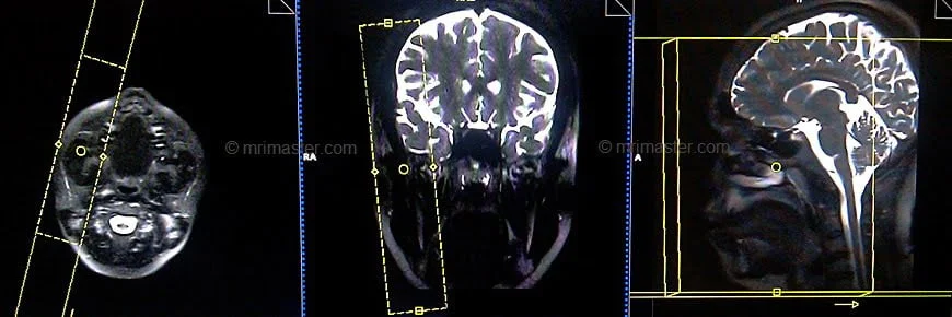
localiser
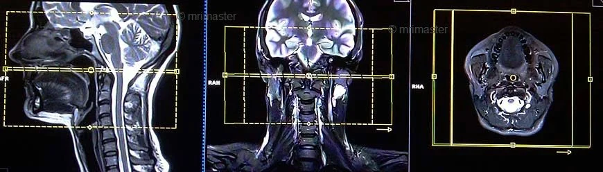
A three-plane localizer must be taken to plan the sequences. Localizers are normally less than 25 seconds, T1-weighted low-resolution scans.
T1 SPACE 3D axial 1MM
Plan the axial 3D block on the sagittal image; angle the positioning block parallel to the hard palate. Check the positioning block in the other two planes. Provide an appropriate angle in the coronal plane (perpendicular to the cervical spine). The slices must be sufficient to cover the entire parotid gland from the glabella down to the angle of the jaw.
Parameters
TR 500-600 | TE 18-20 | SLICE 1MM | FLIP T1 vre | PHASE R>L | MATRIX 256X256 | FOV 170-190 | GAP 10% | NEX(AVRAGE) 2 |
T2 STIR SPACE 3D axial 1mm
Plan the axial 3D block on the sagittal image; angle the positioning block parallel to the hard palate. Check the positioning block in the other two planes. Provide an appropriate angle in the coronal plane (perpendicular to the cervical spine). The slices must be sufficient to cover the entire parotid gland from the glabella down to the angle of the jaw.
Parameters
TR 3000-4000 | TE 250-300 | SLICE 1MM | TI 160 | PHASE R>L | MATRIX 224X224 | FOV 170-200 | GAP 10% | NEX(AVRAGE) 2 |
T2 HASTE axial
Plan the axial slices on the sagittal image; angle the positioning block parallel to the hard palate. Check the positioning block in the other two planes. Provide an appropriate angle in the coronal plane (perpendicular to the cervical spine). The slices must be sufficient to cover the entire parotid gland from glabella down to the angle of the jaw.

Parameters
TR 8000-9000 | TE 250 | FLIP 30 | NEX 4 | SLICE 3MM | MATRIX 256×256 | FOV 220-230 | PHASE R>L | GAP 10% | TI 150 |
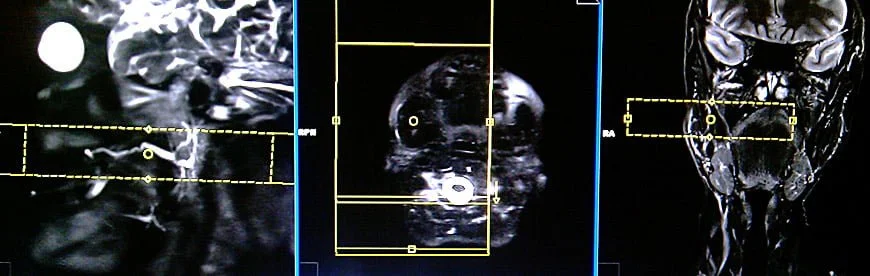
T2 HASTE THICK SLAB localizer 60mm
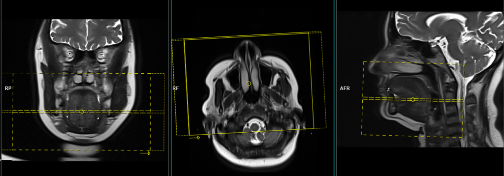
Plan the oblique sagittal thick slab localizer on the axial HASTE images. Position the planning block over the duct, parallel to the Zygomatic Arch. Check the positioning block in the other two planes. Position the planning block over the duct in a manner parallel to the Zygomatic Arch. Verify the positioning block in the other two planes for accuracy. In the coronal plane, an appropriate angle should be set, ensuring it remains parallel to both the Zygomatic Arch and the mental protuberance of the mandible. The slice thickness should be sufficient to encompass the entire duct, from the skin to the upper molar crowns. This localizer serves as a crucial reference for precise localization of the duct during subsequent slice planning.
Parameters
TR 7000-8000 | TE 500 | FLIP 30 | NEX 2 | SLICE 60MM | MATRIX 256×256 | FOV 250-300 | PHASE A>P | PLANE SAG OBL | TI 150 |
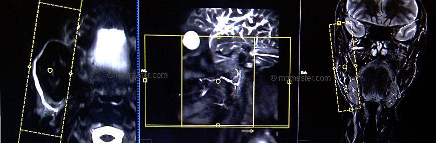
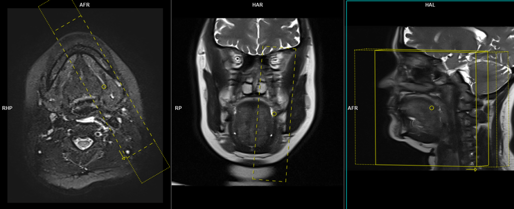
T2 HASTE THICK SLAB axial oblique 20mm
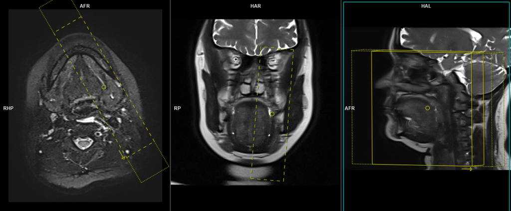
Plan the axial oblique thin slab (20mm) on the HASTE sagittal localizer. Position the planning block parallel to the duct. Check the positioning block in the axial planes and center it over the duct, ensuring it aligns with the right side duct for right parotid sialogram and the left side duct for left parotid sialogram. Adjust the slice thickness as necessary to cover the entire duct adequately. Maintain a small FOV (110mm) to achieve a high-resolution view of the duct. Additionally, ensure sufficient oversampling to prevent wrap-around artifacts from the opposite ducts.
Parameters
TR 7000-8000 | TE 500 | FLIP 30 | NEX 10 | SLICE 20MM | MATRIX 256×256 | FOV 110 | PHASE R>L | PLANE axi OBL | TI 130 |
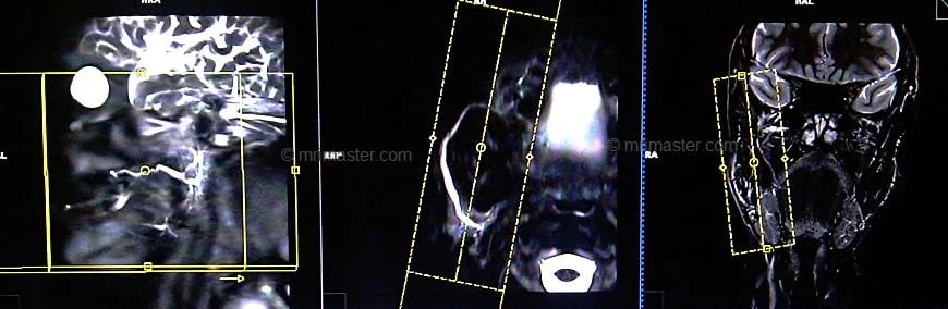
T2 HASTE THICK SLAB sagittal oblique 25mm
Plan the sagittal oblique thin slab (25mm) slice on the high-resolution axial HASTE thick slab image. Position the planning block parallel to the duct, and check its positioning in the other two planes. Provide an appropriate angle in the coronal plane, ensuring it is parallel to the Zygomatic arch and mental protuberance of the mandible. The slice thickness must be sufficient to cover the entire duct; increase the slice thickness if necessary. Keep the FOV small enough (120mm) to obtain a high-resolution view of the duct. Ensure sufficient oversampling is applied to avoid wrap-around artifacts.
Parameters
TR 7000-8000 | TE 500 | FLIP 30 | NEX 10 | SLICE 25MM | MATRIX 256×256 | FOV 110 | PHASE R>L | PLANE axi OBL | TI 130 |
T2 SPACE 3D sagittal oblique .8mm
Plan the sagittal oblique 3D slab on the high-resolution axial HASTE slice; align the planning block parallel to the duct. Check the positioning block in the other two planes. Provide an appropriate angle in the coronal plane (parallel to the line along the Zygomatic arch and mental protuberance of the mandible). Ensure that the slices are sufficient to cover the entire duct from the skin to the upper molar crowns. The Field of View (FOV) must be small enough (180mm) to obtain a high-resolution view of the duct. Sufficient oversampling must be applied to avoid wrap-around artifacts.
Parameters Space
TR 3000-4000 | TE 390 | FLIP 30 | NEX 2 | SLICE .8MM | MATRIX 256×256 | FOV 180 | PHASE R>L | PLANE SAG OBL | TI nil |
SPACE : SPACE, an advanced variant of the 3D Turbo spin echo, employs non-selective, short refocusing pulse trains with RF pulses of varying flip angles, enabling exceptionally high turbo factors and sampling efficiency. Consequently, it achieves rapid acquisition of high-resolution isotropic images. In the context of sialography, SPACE sequence is utilized with a long TR (3000) and TE (400) to emphasize fluid visibility and suppress signals from surrounding tissues. This tailored approach ensures efficient imaging with enhanced contrast for accurate evaluation of the salivary ducts and surrounding structures.
localiser
CLICK THE SEQUENCES BELOW TO CHECK THE SCANS
Submandibular Sialogram
RecommendedSubmandibular Sialogram Protocols and Planning
Localizer
A three-plane localizer must be taken to plan the sequences. Localizers are normally less than 25 seconds, T1-weighted low-resolution scans.
T1 SPACE 3D axial 1MM
Plan the axial 3D block on the sagittal localizer; angle the positioning block parallel to the hard palate. Check the positioning block in the other two planes. Provide an appropriate angle in the coronal plane (perpendicular to the cervical spine). Ensure that the slices are sufficient to cover the submandibular gland from the nose tip down to the vocal cord.

Parameters
TR 500-600 | TE 18-20 | SLICE 1MM | FLIP T1 vre | PHASE R>L | MATRIX 256X256 | FOV 170-190 | GAP 10% | NEX(AVRAGE) 2 |
T2 HASTE axial
Plan the axial slices on the sagittal localiser; angle the positioning block parallel to the hard palate. Check the positioning block in the other two planes. Provide an appropriate angle in the coronal plane (perpendicular to the cervical spine). Ensure that the slices are sufficient to cover the submandibular gland from the nose tip down to the vocal cord.
Parameters
TR 8000-9000 | TE 250 | FLIP 30 | NEX 4 | SLICE 3MM | MATRIX 256×256 | FOV 220-230 | PHASE R>L | GAP 10% | TI 130 |
T2 STIR SPACE 3D axial 1mm
Plan the axial 3D block on the sagittal localizer; angle the positioning block parallel to the hard palate. Check the positioning block in the other two planes. Provide an appropriate angle in the coronal plane (perpendicular to the cervical spine). Ensure that the slices are sufficient to cover the submandibular gland from the nose tip down to the vocal cord.
Parameters
TR 3000-4000 | TE 250-300 | SLICE 1MM | TI 160 | PHASE R>L | MATRIX 224X224 | FOV 170-200 | GAP 10% | NEX(AVRAGE) 2 |
Before moving on to the next step, administer 10ml of lime juice or Carbex Citric acid 1g/10ml oral solution to activate the salivary glands. To do this, carefully slide the table out and remove the head coil. Then, gently pour the solution into the patient’s mouth, instructing them to remain completely still during the process. Ask the patient to swallow the entire solution and then reattach the head coil.
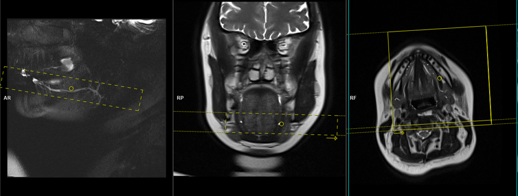
T2 HASTE sagittal oblique localizer 60mm
Plan the oblique sagittal thick slab localizer on the axial HASTE images; position the planning block over the duct, parallel to the body of the mandible. Check the positioning block in the other two planes. Provide an appropriate angle in the coronal plane (parallel to the line along the Zygomatic arch and the mental protuberance of the mandible). The slice thickness must be sufficient to cover the entire duct. This localizer is used to precisely locate the duct for further slice planning.
Parameters
| TR7000-8000 | TE 500 | FLIP 30 | NEX 2 | SLICE 60MM | MATRIX 256×256 | FOV 250-300 | PHASE A>P | PLANE SAG OBL | TI 130 |
T2 HASTE axial oblique 20mm
Plan the axial oblique thin slab (20mm) on the HASTE thick slab localizer. Position the planning block parallel to the duct. Check the positioning block in the axial planes and center it over the duct (right submandibular duct for right-side sialogram and left submandibular duct for left-side sialogram). Ensure that the slice thickness is sufficient to cover the entire duct (increase slice thickness if needed). The FOV must be small enough (110mm) to achieve a high-resolution view of the duct. Provide sufficient oversampling to avoid wrap-around artifacts from the opposite ducts.
Parameters
| TR7000-8000 | TE 500 | FLIP 30 | NEX 8 | SLICE 20MM | MATRIX 256×256 | FOV 110 | PHASE R>L | PLANE axi OBL | TI 130 |
T2 HASTE sagittal oblique 20mm
Plan the sagittal oblique thin slab (20mm) slice on the high-resolution axial HASTE thick slab image, aligning the planning block parallel to the duct. Verify the positioning block in the other two planes. Provide an appropriate angle in the coronal plane (parallel to the line along the Zygomatic arch and mental protuberance of the mandible). Ensure that the slice thickness is sufficient to cover the entire duct (increase slice thickness if needed). Set the FOV to a small enough value (120mm) to achieve a high-resolution view of the duct. Use sufficient oversampling to prevent wrap-around artifacts.
Parameters
| TR7000-8000 | TE 500 | FLIP 30 | NEX 10 | SLICE 20MM | MATRIX 256×256 | FOV 110 | PHASE R>L | PLANE axi OBL | TI 130 |
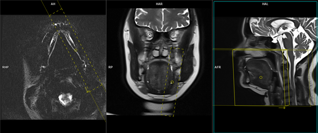
T2 SPACE 3D sagittal oblique 0.8MM
Plan the sagittal oblique 3D slab on the high-resolution axial HASTE thick slab image, angling the planning block parallel to the duct. Check the positioning block in the other two planes. Provide an appropriate angle in the coronal plane (parallel to the line along Zygomatic arch and mental protuberance of the mandible). The slices must sufficiently cover the entire duct from the skin to the upper molar crowns. The Field of View (FOV) must be small enough (200mm) to obtain a high-resolution view of the duct. Adequate oversampling must be applied to avoid wrap-around artifacts.
Parameters
TR 2000-3000 | TE 290 | FLIP 30 | NEX 2 | SLICE .8MM | MATRIX 256×256 | FOV 180 | PHASE R>L | PLANE SAG OBL | TI nil |