MRI Gynaecology Pelvis (Endometrial CA Protocol)
Indications for MRI female pelvis endometrial scans
- For the evaluation of pelvic floor defects associated with urinary or fecal incontinence
- Prior to m yomectomy, hysterectomy, or uterine artery embolization
- For the evaluation and staging of fallopian tube malignancies
- For the evaluation of a congenital anomaly of female pelvis
- For the evaluation and staging of soft tissue origin sarcomas
- For the evaluation and staging of endometrial malignancies
- For the evaluation of recurrence of tumours
- For the evaluation of pelvic pain or mass
- Vaginal bleeding
Contraindications for endometrial MRI scans
- Any electrically, magnetically or mechanically activated implant (e.g. cardiac pacemaker, insulin pump biostimulator, neurostimulator, cochlear implant, and hearing aids)
- Intracranial aneurysm clips (unless made of titanium)
- Pregnancy (risk vs benefit ratio to be assessed)
- Ferromagnetic surgical clips or staples
- Metallic foreign body in the eye
- Metal shrapnel or bullet
Patient preparation for endometrial MRI scans
- A satisfactory written consent form must be taken from the patient before entering the scanner room
- Ask the patient to remove all metal objects including keys, coins, wallet, cards with magnetic strips, jewellery, hearing aid and hairpins
- Ask the patient to undress and change into a hospital gown
- Contrast and buscopan injection risk and benefits must be explained to the patient before the scan
- Gadolinium should only be given to the patient if GFR is > 30
- An intravenous line must be placed with extension tubing extending out of the magnetic bore
- Claustrophobic patients may be accompanied into the scanner room e.g. by staff member or relative with proper safety screening
- Offer earplug or headphones possibly with music for extra comfort.
- Explain the procedure to the patient and answer questions
- Note down the weight of the patient
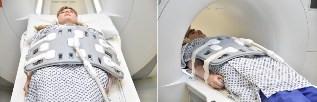
Positioning for endometrial MRI scans
- Position the patient in supine position with head pointing towards the magnet (head first supine)
- Position the patient over the spine coil and place the body coil over abdomen and pelvis (nipple down to three inches below symphysis pubis)
- Securely tighten the body coil using straps to prevent respiratory artefacts
- Give a pillow under the head and cushions under the legs for extra comfort
- Centre the laser beam localiser over the iliac crest
- Register the patient in the scanner as head first supine
Recommended Endometrial Cancer(CA) MRI Protocols and Planning
Endometrial MRI scans localiser
A three plane localiser must be taken in the beginning to localise and plan the sequences. Localisers are normally less than 25sec. T1 weighted low resolution scans.

Pause for buscopan injection
Warning
* Buscopan injection should not be administered to patients with myasthenia gravis, megacolon, narrow angle glaucoma, tachycardia, prostatic enlargement with urinary retention, mechanical stenoses in the region of the gastrointestinal tract or paralytic ileus.*
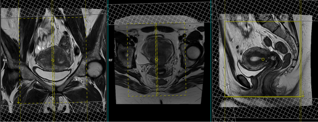
T2 tse sagittal 3mm SFOV
Plan the sagittal slices on the axial plane and angle the positioning block parallel to the line along the linea alba and median sacral crest. Verify the positioning block in the other two planes. In the coronal plane, an appropriate angle must be given, which should be parallel to the lumbosacral spine. Make sure that the slices cover the entire pelvis from the right acetabulum to the left acetabulum. The field of view (FOV) should be sufficiently large to encompass the entire pelvis, typically ranging from 270mm to 300mm. To minimize artifacts caused by arterial pulsation, peristalsis, and breathing, consider adding saturation bands on top and in front of the sagittal block. Ensure an adequate level of phase oversampling to prevent any wrap-around artifacts.
Due to the increased signal-to-noise ratio (SNR) in new generation scanners, motion artifacts can be significant when acquiring images in the anterior-posterior phase direction. This is primarily attributed to the movement of abdominal fat, which exhibits higher signal intensity and can cause ghosting effects over the sagittal images. Therefore, to mitigate this issue, scans are typically performed using a head-to-feet phase direction.
Parameters
TR 3000-4000 | TE 100-120 | SLICE 3 MM | FLIP 130-150 | PHASE A>P | MATRIX 320X320 | FOV 270-300 | GAP 10% | NEX(AVRAGE) 4 |
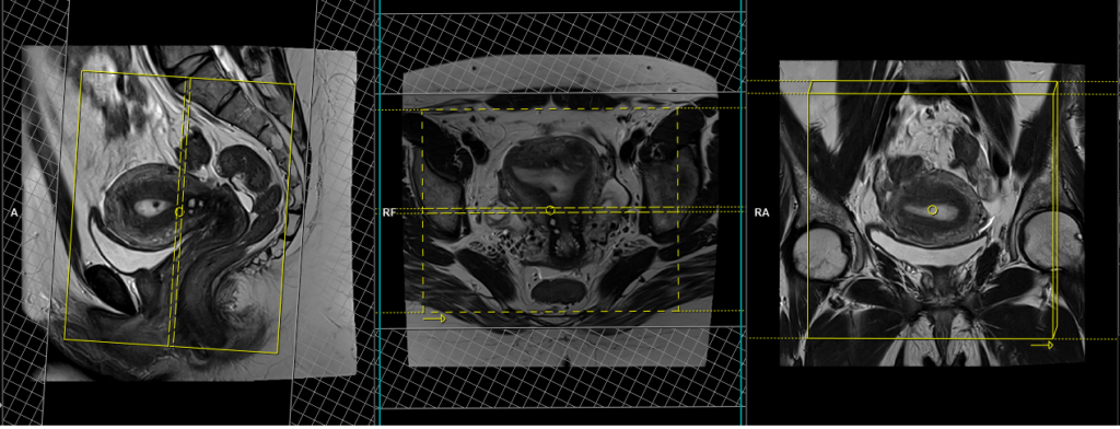
T2 tse axial 6 mm largeFOV
Plan the large field of view (FOV) axial slices on the coronal plane, position the block parallel to the line along the right and left iliac crest. The positioning block should also be checked in the other two planes. An appropriate angle needs to be established in the sagittal plane, which is perpendicular to the lumbar spine. The slices must be sufficient to cover the entire lower abdomen and pelvis, ranging from the middle of the kidneys down to the symphysis pubis. The FOV should be large enough to cover the entire pelvis, typically ranging from 350mm to 400mm. Adding saturation bands on top of the axial block can help reduce artifacts caused by arterial pulsation and breathing. Large FOV scans are usually performed to evaluate the para-aortic and pre-sacral nodes.

Parameters
TR 5000-6000 | TE 100-120 | SLICE 6 MM | FLIP 130-150 | PHASE R>L | MATRIX 384X384 | FOV 350-400 | GAP 10% | NEX(AVRAGE) 2 |
T1 tse axial 6 mm Large FOV
Plan the large field of view (FOV) axial slices on the coronal plane, position the block parallel to the line along the right and left iliac crest. The positioning block should also be checked in the other two planes. An appropriate angle needs to be established in the sagittal plane, which is perpendicular to the lumbar spine. The slices must be sufficient to cover the entire lower abdomen and pelvis, ranging from the middle of the kidneys down to the symphysis pubis. The FOV should be large enough to cover the entire pelvis, typically ranging from 350mm to 400mm. Adding saturation bands on top of the axial block can help reduce artifacts caused by arterial pulsation and breathing. Large FOV scans are usually performed to evaluate the para-aortic and pre-sacral nodes.
Parameters
TR 400-600 | TE 15-25 | SLICE 6 MM | FLIP 130 | PHASE R>L | MATRIX 384X384 | FOV 350-400 | GAP 10% | NEX(AVRAGE) 2 |
T2 stir coronal 5 mm LARGE FOV
Plan the large field of view (FOV) coronal slices on the sagittal plane and position the block parallel to the lumbar spine. The positioning block should also be checked in the other two planes. An appropriate angle needs to be established in the axial plane, which runs parallel to the right and left hip joint. The slices must be sufficient to cover the entire abdomen and pelvis, ranging from the anterior abdominal wall to the sacrum. The FOV must be large enough to cover the abdomen and pelvis (typically 380mm-400mm). Large FOV scans are usually performed to evaluate the local spread of the pathology and assess the para-aortic and pre-sacral nodes.

Parameters
TR 4000-6000 | TE 110 | FLIP 160 | NEX 2 | SLICE 5MM | MATRIX 384X320 | FOV 380-400 | PHASE R>L | GAP 10% | TI 150 |
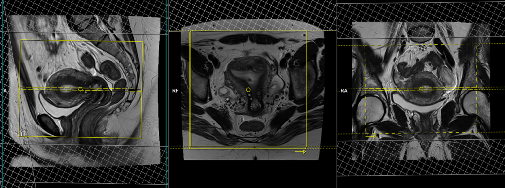
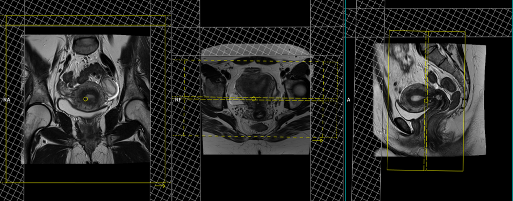
T2 tse axial oblique 3mm SFOV of uterus
Plan the axial oblique slices on the sagittal plane, ensuring that the position block is angled perpendicular to the endometrium. Verify the positioning block in the other two planes. Provide an appropriate angle in theaxial plane (straight across the uterus). The slices must be sufficient to cover the entire uterus and ovaries. Adding saturation bands on top and in front of the axial block will help reduce artifacts caused by arterial pulsation and breathing. Ensure an adequate level of phase oversampling to prevent any wrap-around artifacts.
Parameters
TR 4000-6000 | TE 100-120 | SLICE 3 MM | FLIP 130-150 | PHASE H>F | MATRIX 320X256 | FOV 180-230 | GAP 10% | NEX(AVRAGE) 5 |
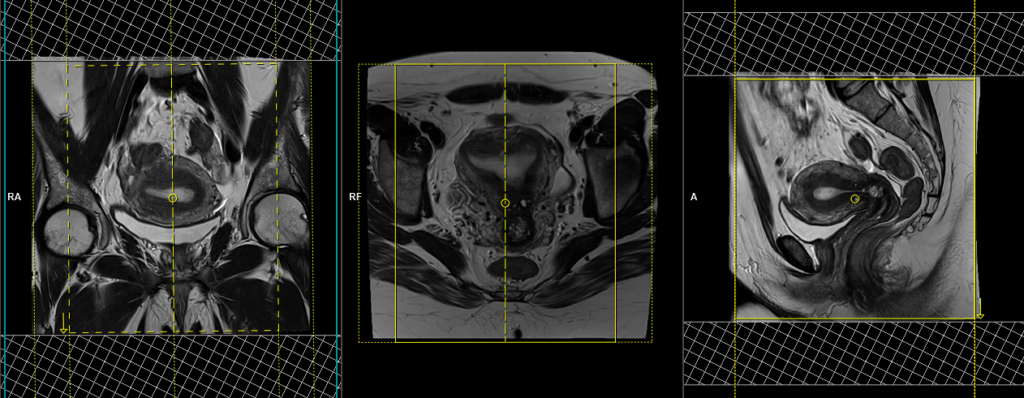
T2 tse coronal oblique 3mm SFOV of uterus
Plan the coronal oblique slices on the sagittal plane, ensuring that the position block is angled parallel to the endometrium. Check the positioning block in the other two planes. Ensure an appropriate angle is set in the axial plane (across the uterus). The slices must be sufficient to cover the entire uterus and ovaries. Adding saturation bands on the top and front of the coronal block will help reduce artifacts caused by arterial pulsation and breathing. Ensure an adequate level of phase oversampling to prevent any wrap-around artifacts.
Due to the increased signal-to-noise ratio (SNR) in new generation scanners, motion artifacts can be significant when acquiring images in the anterior-posterior phase direction. This is primarily attributed to the movement of abdominal fat, which exhibits higher signal intensity and can cause ghosting effects over the sagittal images. Therefore, to mitigate this issue, scans are typically performed using a right-to-left phase direction.
Parameters
TR 3000-4000 | TE 100-120 | SLICE 3 MM | FLIP 130-150 | PHASE R>L | MATRIX 320X256 | FOV 180-230 | GAP 10% | NEX(AVRAGE) 5 |
T1 tse fat sat axial oblique 3mm SFOV of uterus
Plan the axial oblique slices on the sagittal plane; angle the position block perpendicular to the endometrium (this angulation can be vary according to the pathology check the normal variation section for the differences in planning). Check the positioning block in the other two planes. An appropriate angle must be given in the coronal plane (perpendicular to the endometrium). Slices must be sufficient to cover the whole uterus and ovaries. Adding saturation bands on top and front of the axial block will reduce artifacts from arterial pulsation and breathing.
Parameters
TR 400-600 | TE 15-25 | SLICE 3 MM | FLIP 130 | PHASE R>L | MATRIX 256X256 | FOV 180-230 | GAP 10% | NEX(AVRAGE) 3 |
DWI epi3scan trace axial 3mm SFOV
Plan the coronal oblique slices on the sagittal plane; angle the position block parallel to the endometrium (this angulation can be vary according to the pathology check the normal variation section for the differences in planning). Check the positioning block in the other two planes. An appropriate angle must be given in the axial plane (straight across the uterus). Slices must be sufficient to cover the whole uterus and ovaries. Adding saturation bands on top and both sides of the block can help minimize artifacts caused by fat signal, arterial pulsation, and breathing.
Parameters
TR 6000-7000 | TE 90 | IPAT ON | NEX 3 5 8 | SLICE 3 MM | MATRIX 192X192 | FOV 200-250 | PHASE R>L | GAP 10% | B VALUE 0 |
Most common indications for contrast enhanced scans
- For the evaluation and staging of endometrial malignancies
T1 VIBE DIXON 3D sagittal dynamic 1 pre 8 post
Plan the sagittal 3D block on the axial plane, angling the positioning block parallel to the endometrium. Check the positioning block in the other two planes. An appropriate angle must be given in the coronal plane (perpendicular to the uterus). Slices must be sufficient to cover the entire pelvis from the right acetabulum to the left acetabulum. The field of view (FOV) must be large enough to encompass the entire pelvis (usually 270mm-300mm). Adding saturation bands on the top and front of the sagittal block will reduce artifacts caused by arterial pulsation and breathing. Ensure an adequate level of slice and phase oversampling to prevent any wrap-around artifacts.
Parameters
TR 4-5 | TE 2-3 | FLIP 10 | NEX 1 | SLICE 2 MM | MATRIX 256X256 | FOV 200-250 | PHASE R>L | DYNAMIC 9 SCANS | IPAT ON |
CLICK THE SEQUENCES BELOW TO CHECK THE SCANS
- localize_3plane1
- T2_TSE_SAGITTAL_SFOV2
- T2_TSE_AXIAL_BIG-FOV_WHOLE PELVIS3
- T1_TSE_AXIAL_BIG FOV_WHOLE PELVIS4
- T2_STIR_CORONAL_BIG FOV5
- T1_TSE_AXIAL_3MM_SFOV6
- T2_TSE_CORONAL_OBLIQUE_SFOV7
- T1_TSE_FAT SAT_AXIAL OBLIQUE_SFOV8
- DWI_EPI_3TRACE_AXIAL OBLIQUE9
- T1_VIBE 3D_FAT SAT_DYNAMIC_SAGITTAL10
- T1_TSE_FAT SAT_AXIAL OBLIQUE_SFOV POST11