MRI Breast Implants
Indications for breast implant MRI scans
- Identified mass with indeterminate characteristics by mammography or sonography in which patient wishes to avoid biopsy
- Staging for chest wall invasion or lymphadenopathy after cancer diagnosis
- Dense breasts with difficult to read mammogram based on visualisation
- Breast implant integrity or breast implant rupture screening
- Palpable mass with negative mammography/sonography
- Axillary node metastases with an unknown primary
- Unexplained swollen breast or breast implant
- To check the response to neoadjuvant chemotherapy
- To check the extent of infiltrating lobular carcinoma
- To check the extent of infiltrating ductal carcinoma
- To check the residual disease post-lumpectomy
- Postoperative tissue reconstruction
- Dense breasts in the high risk patient
- Surveillance of high-risk patients
- Contralateral breast screening
- Determine extent of disease
- Recurrence of breast cancer
- Lesion characterisation
Contraindications
- Any electrically, magnetically or mechanically activated implant (e.g. cardiac pacemaker, insulin pump biostimulator, neurostimulator, cochlear implant, and hearing aids)
- Intracranial aneurysm clips (unless made of titanium)
- Pregnancy (risk vs benefit ratio to be assessed)
- Ferromagnetic surgical clips or staples
- Metallic foreign body in the eye
- Metal shrapnel or bullet
Patient preparation for breast implant MRI scan
- A satisfactory written consent form must be taken from the patient before entering the scanner room
- Ask the patient to change to a hospital gown with the open side of the gown in the front (its important to wear the gown in proper way because the patient will be laying down on top of the coil with open gown so they can place the breast in the coil)
- Ask the patient to remove all metal objects including keys, coins, wallet, any cards with magnetic strips, jewellery, hearing aid and hairpins
- If possible offer some one in the scanner room for claustrophobic patient (e.g. relative or staff ).
- An intravenous line must be placed with extension tubing extending out of the magnetic bore
- Contrast injection risk and benefits must be explained to the patient before the scan.
- Gadolinium should only be given to the patient if GFR is > 30
- Offer earplugs or headphones, possibly with music for extra comfort
- Properly explain the procedure to the patient
- Instruct the patient to keep still
- Note the weight of the patient
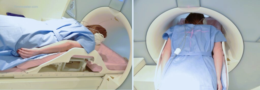
Positioning for breast implant MRI scans
- Head first prone
- Position the patient with breast inside the breast coil and both arms by side of the body (be careful about the intravenous line when you position the patient)
- Give cushions under the legs and under the forehead for extra comfort
- Centre the laser beam localizer over the mid chest (T6-T7 level)
Recommended Breast Implant MRI Protocols and Planning
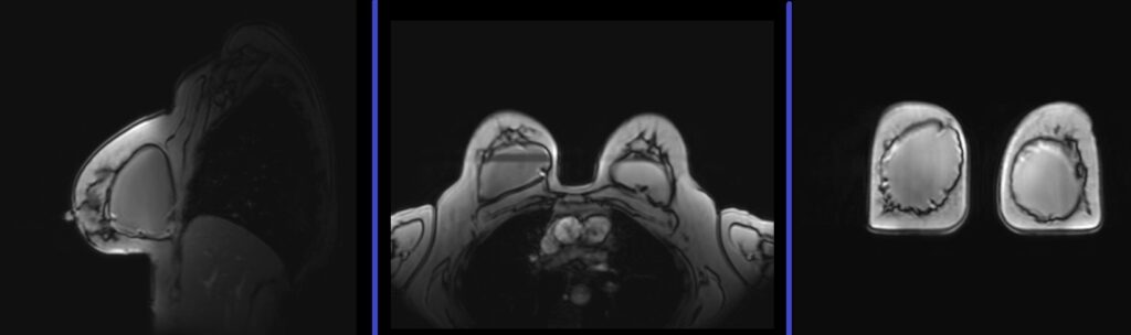
Breast implant MRI localiser
A three-plane localizer must be taken to plan the sequences. Localizers are normally less than 25 seconds and consist of T1-weighted low-resolution scans.
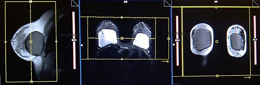
T2 SPACE 3D axial 1MM
Plan the axial slices on the sagittal plane and align the position block parallel to the breast. Verify the positioning block in the other two planes. Ensure an appropriate angle is set in the coronal plane, parallel to the right and left nipples. The slices should be sufficient to cover the entire breast. To prevent wrap-around artifacts, oversampling of both the slice and phase should be applied. Phase direction in the axial scans must be right to left, this is to avoid the artefacts from chest and heart motion.
If 3D sequences are unavailable on your scanner, please utilize 2D T2 axial scans with a slice thickness of 2 to 3mm.

Parameters T2 SPACE 3D
TR 1500-2000 | TE 94 | FLIP 170 | NXA 1.4 | SLICE 1.5 MM | MATRIX 320X256 | FOV 350-390 | PHASE R>L | GAP 10% | OVERSAMPLE 10% and 20% |
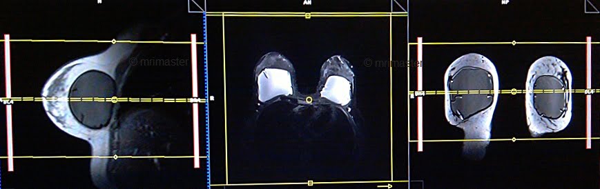
T1 flash 3D axial non fat sat 1mm
Plan the axial slices on the sagittal plane and align the position block parallel to the breast. Verify the positioning block in the other two planes. Ensure an appropriate angle is set in the coronal plane, parallel to the right and left nipples. The slices should be sufficient to cover the entire breast. To prevent wrap-around artifacts, oversampling of both the slice and phase should be applied. Phase direction in the axial scans must be right to left, this is to avoid the artefacts from chest and heart motion.
Parameters
TR 6-7 | TE 3-4 | FLIP 20 | NEX 1 | SLICE 1MM | MATRIX 384X320 | FOV 350 | PHASE R>L | OVERSAMPLE 30% | IPAT ON |
T2 stir TI 130 coronal
Plan the coronal slices on the axial plane and position the block perpendicular to the right and left breast. Verify the positioning block in the other two planes. Ensure an appropriate angle is set in the sagittal plane, perpendicular to the right and left breast. The slices should adequately cover the entire breast from the nipple to the axilla. In axial scans, the phase direction should be from right to left to avoid artifacts caused by motion from the chest and heart.
Parameters
TR 4000-5000 | TE 110 | FLIP 150 | NEX 2 | SLICE 3 MM | MATRIX 320X320 | FOV 350-390 | PHASE R>L | WATER SAT OFF | TI 130 |
T2 STIR with water suppression axial
Plan the axial slices on the sagittal plane and align the position block parallel to the breast. Verify the positioning block in the other two planes. Ensure an appropriate angle is set in the coronal plane, parallel to the right and left nipples. The slices should be sufficient to cover the entire breast. To prevent wrap-around artifacts, oversampling of both the slice and phase should be applied. Phase direction in the axial scans must be right to left, this is to avoid the artefacts from chest and heart motion.
Parameters
TR 4000-5000 | TE 110 | FLIP 130 | NEX 2 | SLICE 3 MM | MATRIX 320X320 | FOV 350-390 | PHASE R>L | WATER SAT ON | TI 130 |
In case you are operating a Siemens scanner, ensure that both STIR and water saturation are activated for this particular sequence.
T2 stir TI 450 or STIR silicon sat axial
Plan the axial slices on the sagittal plane and align the position block parallel to the breast. Verify the positioning block in the other two planes. Ensure an appropriate angle is set in the coronal plane, parallel to the right and left nipples. The slices should be sufficient to cover the entire breast. To prevent wrap-around artifacts, oversampling of both the slice and phase should be applied. Phase direction in the axial scans must be right to left, this is to avoid the artefacts from chest and heart motion.
Parameters
TR 4000-5000 | TE 110 | FLIP 130 | NEX 2 | SLICE 3 MM | MATRIX 320X320 | FOV 350-390 | PHASE R>L | GAP 10% | TI 450 |
Why two different TIs ?
TI 450 is used to suppress the signals form silicon where us TI 130 is used to suppress the signals from fat.
If you choose the Silicon saturation sequence with the silicon sat pulse, please adhere to the following instructions.
Silicon Saturation pulse
In MRI (Magnetic Resonance Imaging), a Fat-Saturation (Fat-Sat) pulse is a short-duration radiofrequency (RF) pulse that is specifically tuned to the resonance frequency of fat molecules. This pulse is applied just before starting an MR imaging sequence. The primary purpose of the Fat-Sat pulse is to selectively nullify or ‘saturate’ the signal from fat molecules while leaving the signal from water and other tissues relatively unaffected.
When the Silicon Saturation pulse option is activated in the sequence, the MRI scanner will display a graph during the frequency adjustment process. The graph will show three distinct peaks in SIEMENS MRI scanners: the first peak corresponds to silicon, the second to fat, and the third to water. The appearance of the graph might vary in scanners from other manufacturers.
The user then needs to select the appropriate peak for suppressing the silicon signal. Once the appropriate peak is chosen, the sequence will suppress the silicon signal, causing silicon to appear dark in the resulting image. Please refer to the picture below for an example of the graph displayed on SIEMENS scanners.

T1 flash axial 3D fat sat dynamic 1 pre and 5 post
Plan the axial slices on the sagittal plane and align the position block parallel to the breast. Verify the positioning block in the other two planes. Ensure an appropriate angle is set in the coronal plane, parallel to the right and left nipples. The slices should be sufficient to cover the entire breast. To prevent wrap-around artifacts, oversampling of both the slice and phase should be applied. Phase direction in the axial scans must be right to left, this is to avoid the artefacts from chest and heart motion.
A dynamic flash 3D fat saturation sequence comprises six flash 1mm 3D scans with a 10-second delay between the first and second scans. The first scan in the dynamic sequence serves as a pre-contrast scan, which is utilized as a subtraction mask for the post-contrast scans. The second through sixth scans are considered post-contrast scans. According to the manufacturer’s instructions and departmental policy, a gadolinium-based contrast agent should be injected at a dose of 0.2ml/kg between the first and second scans, specifically during the 10-second delay period.
Parameters
TR 4-5 | TE 2 | FLIP 12 | NEX 1 | SLICE 1 MM | MATRIX 448X320 | FOV 350-380 | PHASE R>L | DYNAMIC 6 SCANS | IPAT ON |
T1 flash 3D fat sat post contrast 1mm
Plan the coronal slices on the axial plane and position the block perpendicular to the right and left breast. Verify the positioning block in the other two planes. Ensure an appropriate angle is set in the sagittal plane, perpendicular to the right and left breast. The slices should adequately cover the entire breast from the nipple to the axilla. In axial scans, the phase direction should be from right to left to avoid artifacts caused by motion from the chest and heart.

Parameters
| TR4-5 | TE 2 | FLIP 12 | NEX 2 | SLICE 1MM | MATRIX 512X512 | FOV 350-360 | PHASE R>L | OVERSAMPLE 30% | IPAT ON |
DWI zoomit \ epi 3 scan trace axial
Plan the axial slices on the sagittal plane and align the position block parallel to the breast. Verify the positioning block in the other two planes. Ensure an appropriate angle is set in the coronal plane, parallel to the right and left nipples. The slices should be sufficient to cover the entire breast. For axial DWI zoomit scans, the phase direction should be from anterior to posterior. This helps avoid artifacts caused by the air-tissue interface by minimizing unwanted areas within the field of view (FOV). To mitigate wrap-around and motion artifacts originating from the chest and heart, it is recommended to apply two saturation bands over the chest region.

Parameters EPI DWI
TR 5000-6000 | TE 90 | IPAT ON | NEX 4 | SLICE 4MM | MATRIX 192X192 | FOV 320-360 | PHASE R>L | GAP 10% | B VALUE 0 |
Zoomit DWI
Zoomit DWI is an advanced MRI imaging technique that leverages Siemens’ TimTX TrueShape platform and the application called Syngo ZOOMit. TimTX TrueShape introduces a new transmit platform with two independent transmitters, enabling flexible switching of RF waveforms and gradient shapes. This dynamic parallel transmission (pTX) capability opens up new possibilities for imaging applications.
Syngo ZOOMit, the first application based on TimTX TrueShape, utilizes the concept of “zooming” in MR imaging. Similar to optical zoom in a camera, ZOOMit allows for exciting a smaller field-of-view (FOV) than the object in the phase-encoding direction, thereby avoiding aliasing artifacts. By reducing the FOV, fewer phase-encoding lines are required, leading to faster scan times, improved spatial resolution in the region of interest, and reduced motion and flow artifacts.
Zoomit DWI offers several advantages over conventional DWI techniques. It employs multiple parallel radiofrequency pulse sequences simultaneously, capturing high signal specifically from the area of interest. This approach reduces folding artifacts, provides better anatomical detail, decreases distortion and blurring, and improves overall image quality. Additionally, it allows for faster screening, increased spatial resolution, and minimized susceptibility artifacts and geometric distortions.
With ZOOMit, radiologists and researchers can selectively image the volume of interest, achieve faster and higher-resolution imaging, enhance diagnostic confidence by detecting and evaluating smaller lesions in challenging areas, and broaden the scope of clinical MR imaging.
