Multiple Sclerosis (MS) MRI Protocol and Planning | MS MRI Brain and Spinal Cord Protocol
Introduction
Multiple sclerosis (MS) is a chronic and potentially disabling neurological disorder that affects the central nervous system (CNS), primarily the brain and spinal cord. It is characterized by the immune system mistakenly attacking the protective covering of nerve fibers, known as myelin, causing inflammation, damage, and disruptions in the transmission of nerve signals. This can result in a wide range of symptoms, including fatigue, difficulty walking, numbness or weakness in limbs, vision problems, pain, and impaired coordination.
Magnetic Resonance Imaging (MRI) plays a pivotal role in the diagnosis and management of multiple sclerosis due to its exceptional ability to visualize the central nervous system in exquisite detail. The importance of MRI in MS diagnosis can be understood from several aspects:
Visualizing Lesions: MS is marked by the presence of lesions or plaques, which represent areas of inflammation, demyelination, and scarring in the CNS. MRI can detect these lesions, their locations, sizes, and patterns, aiding in differentiating MS from other conditions with similar symptoms.
Early Detection and Monitoring: Early diagnosis of MS is crucial for initiating timely treatment and preventing further damage. MRI can identify subtle changes in the CNS before clinical symptoms become apparent, enabling early intervention. Regular MRI scans over time allow physicians to monitor disease progression and response to treatment.
Lesion Characterization: Advanced MRI techniques, such as diffusion-weighted imaging (DWI) and spectroscopy, provide insights into the composition and microstructural changes of lesions. This information helps distinguish between active inflammation, ongoing demyelination, and tissue repair, guiding treatment decisions.
Guiding Treatment Strategies: MRI findings assist healthcare professionals in tailoring treatment plans for MS patients. By assessing disease activity and burden, clinicians can make informed decisions about disease-modifying therapies (DMTs) and adjust treatment regimens as needed.
Research and Clinical Trials: MRI data contributes significantly to MS research and clinical trials. It aids in understanding disease mechanisms, developing new therapies, and evaluating treatment efficacy. MRI measures serve as objective endpoints in clinical trials, providing quantifiable data for assessing treatment outcomes.
Indications
- Multiple Sclerosis (MS) or other demyelinating diseases.
Contraindications
- Any electrically, magnetically or mechanically activated implant (e.g. cardiac pacemaker, insulin pump biostimulator, neurostimulator, cochlear implant, and hearing aids)
- Intracranial aneurysm clips (unless made of titanium)
- Pregnancy (risk vs benefit ratio to be assessed)
- Ferromagnetic surgical clips or staples
- Metallic foreign body in the eye
- Metal shrapnel or bullet
Patient preparation for Multiple Sclerosis (MS) MRI
- A satisfactory written consent form must be taken from the patient before entering the scanner room
- Ask the patient to remove all metal objects including keys, coins, wallet, cards with magnetic strips, jewellery, hearing aid and hairpins
- Ask the patient to undress and change into a hospital gown
- Contrast injection risk and benefits must be explained to the patient before the scan
- Gadolinium should only be given to the patient if GFR is > 30
- If possible provide a chaperone for claustrophobic patients (e.g. relative or staff )
- Offer earplugs or headphones, possibly with music for extra comfort
- Explain the procedure to the patient
- Instruct the patient to keep still
- Note the weight of the patient
Positioning for Multiple Sclerosis (MS) MRI
- Position patient in the supine position with the head pointing towards the magnet (head first supine)
- Position the patient in the head, neck and spine coils. Place the head, neck and body coil over the patient covering the anatomy from the vertex of the skull down to the lower intercostal border.
- Give cushions under the legs for extra comfort.
- Centre the laser beam localiser over the glabella

Recommended Multiple Sclerosis (MS) MRI Protocols and Planning
Localiser brain
A three-plane localizer must be taken at the beginning to localize and plan the sequences. Localizers are usually less than 25 seconds and are T1-weighted low-resolution scans.

T2 tse axial 3mm
A slice thickness of 3mm or smaller is essential to identify minor MS lesions. Nevertheless, achieving this might be challenging in older generation scanners because of their utilization of reduced gradients and time constraints. In such instances, a slice thickness of up to 5mm could be employed.
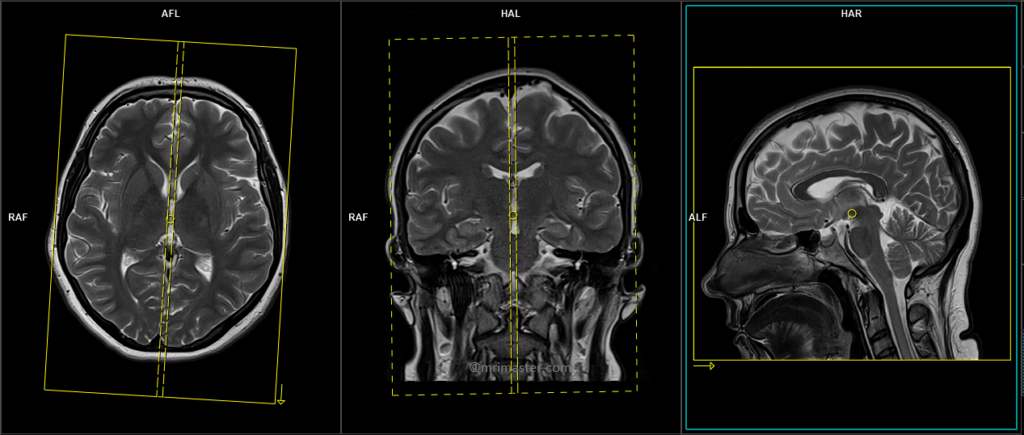
Plan the axial slices on the sagittal plane and position the block parallel to the genu and splenium of the corpus callosum. Verify the positioning block in the other two planes and ensure that an appropriate angle is maintained in the coronal plane, making it perpendicular to the line of the midline of the brain and the 4th ventricle. Ensure that the number of slices is sufficient to cover the entire brain from the vertex to the line of the foramen magnum.

Parameters
TR 4000-5000 | TE 100-120 | SLICE 3MM | FLIP 130-150 | PHASE R>L | MATRIX 256X256 | FOV 210-230 | GAP 10% | NEX(AVRAGE) 2 |
T2 FLAIR axial 3mm
Plan the axial slices on the sagittal plane and position the block parallel to the genu and splenium of the corpus callosum. Verify the positioning block in the other two planes and ensure that an appropriate angle is maintained in the coronal plane, making it perpendicular to the line of the midline of the brain and the 4th ventricle. Ensure that the number of slices is sufficient to cover the entire brain from the vertex to the line of the foramen magnum.
Parameters
TR 7000-9000 | TE 110 | FLIP 130 | NEX 4 | SLICE 3MM | MATRIX 256X256 | FOV 210-230 | PHASE H>F | GAP 10% | TI 2500 |
T1 axial 3mm or 3D T1 SPACE 3D 1mm
Plan the axial block on the sagittal plane and position the block parallel to the genu and splenium of the corpus callosum. Verify the positioning block in the other two planes and ensure that an appropriate angle is maintained in the coronal plane, making it perpendicular to the line of the midline of the brain and the 4th ventricle. Ensure that the number of slices is sufficient to cover the entire brain from the vertex to the line of the foramen magnum.
Parameters T1 TSE
TR 500-600 | TE 15-25 | SLICE 3MM | FLIP 90 | PHASE R>L | MATRIX 256X256 | FOV 210-230 | GAP 10% | NEX(AVRAGE) 2 |
T2 FLAIR sagittal 3mm or SPACE 3D FLAIR 1mm
Plan the axial slices on the sagittal plane; angle the position block parallel to the genu and splenium of the corpus callosum. Slices must be sufficient to cover the whole brain from the vertex to the line of the foramen magnum. Check the positioning block in the other two planes. An appropriate angle must be given in coronal plane on a tilted head (perpendicular to the line of 3rd ventricle and brain stem).
Parameters T2 TSE
TR 7000-9000 | TE 110 | FLIP 130 | NEX 2 | SLICE 3 MM | MATRIX 256X256 | FOV 210-230 | PHASE R>L | GAP 10% | TI 2500 |
RESOLVE DWI axial
Plan the axial slices on the sagittal plane and position the block parallel to the genu and splenium of the corpus callosum. Verify the positioning block in the other two planes and ensure that an appropriate angle is maintained in the coronal plane, making it perpendicular to the line of the midline of the brain and the 4th ventricle. Ensure that the number of slices is sufficient to cover the entire brain from the vertex to the line of the foramen magnum.
RESOLVE DWI: RESOLVE is an advanced technique used to obtain high-quality and high-resolution DWI (diffusion-weighted imaging) images, particularly in body regions affected by susceptibility artifacts. It offers sharp imaging with minimal distortions and provides excellent spatial resolution. RESOLVE is especially valuable for evaluating smaller lesions in a wide range of DWI and DTI (diffusion tensor imaging) examinations. By combining RESOLVE with Simultaneous Multi-Slice (SMS) acceleration, acquisition time can be significantly reduced, improving both speed and imaging capabilities. RESOLVE finds application in various clinical fields, including neurology, oncology, and pediatric imaging. Its outstanding balance between imaging speed and quality makes it superior to other diffusion-weighted imaging sequences. Benefits of RESOLVE include high-quality DWI and DTI, reduced susceptibility and blurring artifacts, insensitivity to motion-induced phase errors, lower specific absorption rate (SAR) compared to TSE-based methods, and compatibility with iPAT for faster scans and further reduced distortions.
Parameters
TR 7000-9000 | TE 70 115 | FLIP 180 | NXA 1 2 | SLICE 3MM | MATRIX 192X192 | FOV 210-230 | PHASE R>L | GAP 10% | B VALUE 0 |
localiser cervicothoracic spine
A three-plane localizer scan should be acquired initially to localize and plan the spine sequences. Localizers typically have a duration of less than 25 seconds and are T1-weighted, low-resolution scans.
This localizer scan can be conducted by either repositioning the patient and centering 2 inches below the sterno-clavicular joint, or by automatically adjusting the table position by approximately 300-350mm towards the head

T2 tse sagittal large FOV localiser for spine counting
This scan aims to localize the spinal cord and assess any spinal cord pathologies at the vertebral body level. This sequence can be completed in under a minute using a restricted slice count and parallel imaging techniques. An alternative approach is to utilize a marker, such as a cod liver oil tablet, positioned at the T4 level for the scans. It is essential to include the marker in the high-resolution, small-field-of-view (FOV) sagittal scans of the upper and lower spinal cord.
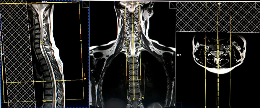
Plan the sagittal slices along the coronal plane, ensuring the positioning block aligns parallel to the spinal cord. Validate the positioning block placement in the remaining two planes. Establish an appropriate angle in the axial plane, running parallel to the hypothetical line intersecting the center of the vertebral body and the spinous process.
Inspect the positioning block within the sagittal plane, ensuring that the field of view (FOV) is adequately large to encompass the entire cervical and thoracic spine, extending from C1 to T12. Normally, an FOV of 480mm should suffice. The slices should span from the lateral border of the right transverse process to that of the left transverse process, effectively covering the spine.
To prevent breathing-related artifacts over the spinal region, position a saturation band over the chest in the sagittal plane. Opt for a phase direction from head to foot to mitigate potential motion artifacts stemming from the chest area.

Parameters
TR 3000-4000 | TE 100-120 | SLICE 4 MM | IPAT ON | PHASE H>F | MATRIX 512X384 | FOV 480-490 | GAP 10% | NEX(AVRAGE) 1 |
T2 tse sagittal 2mm 270-280 FOV or Isotropic 3D T2 SPACE .9mm
Utilizing thin slices and small fields of view is essential for spinal cord imaging, facilitating the detection of small multiple sclerosis (MS) lesions. Modern practice involves substituting TSE scans with an isotropic 3D sequence featuring a slice thickness of 0.9mm.
Plan the sagittal slices along the coronal plane and align the position block parallel to the spinal cord. Verify the positioning block in the other two planes. Ensure an appropriate angle is applied in the axial plane, maintaining parallelism with the imaginary line connecting the center of the vertebral body and the spinous process.
Evaluate the position block in the sagittal plane, ensuring that the field of view (FOV) is sufficiently large to encompass the upper spinal cord from the pons down to T5. Typically, an FOV ranging from 270 to 280mm should prove satisfactory. The slices should adequately encompass the spinal cord from side to side.
To prevent swallowing artifacts, position a saturation band over the neck, situated in front of the esophagus within the sagittal plane. Opt for a phase direction from head to foot to mitigate motion artifacts originating from the neck.
Parameters
TR 3000-4000 | TE 100-120 | SLICE 2 MM | FLIP 130-150 | PHASE H>F | MATRIX 320X320 | FOV 270-280 | GAP 10% | NEX(AVRAGE) 4 |
T1 tse sagittal 2mm 270-280 FOV or Isotropic 3D T1 .9mm
Plan the sagittal slices along the coronal plane and align the position block parallel to the spinal cord. Verify the positioning block in the other two planes. Ensure an appropriate angle is applied in the axial plane, maintaining parallelism with the imaginary line connecting the center of the vertebral body and the spinous process.
Evaluate the position block in the sagittal plane, ensuring that the field of view (FOV) is sufficiently large to encompass the upper spinal cord from the pons down to T5. Typically, an FOV ranging from 270 to 280mm should prove satisfactory. The slices should adequately encompass the spinal cord from side to side.
To prevent swallowing artifacts, position a saturation band over the neck, situated in front of the esophagus within the sagittal plane. Opt for a phase direction from head to foot to mitigate motion artifacts originating from the neck.

Parameters
TR 400-600 | TE 15-25 | SLICE 2 MM | FLIP 150 | PHASE H>F | MATRIX 320X320 | FOV 270-280 | GAP 10% | NEX(AVRAGE) 4 |
T2 TSE Axial block 3mm 150- 160 FOV
Axial scans are only performed over spinal cord pathologies e.g. MS lesions
Plan the axial slices within the sagittal plane, positioning the block perpendicular to the spinal cord. When dealing with a tilted or scoliotic spine, ensure an appropriate angle is applied in the coronal plane, aligning parallel to the intervertebral disc spaces. The number of slices should adequately cover the pathological area or cervical cord. In the sagittal plane, position a saturation band over the neck, in front of the esophagus, to prevent swallowing artifacts

Parameters
TR 3000-4000 | TE 100-120 | SLICE 3 MM | FLIP 130-150 | PHASE A>P | MATRIX 256X256 | FOV 150-160 | GAP 10% | NEX(AVRAGE) 4 |
T1 TSE Axial block 3mm 150- 160 FOV
Plan the axial slices within the sagittal plane, positioning the block perpendicular to the spinal cord. When dealing with a tilted or scoliotic spine, ensure an appropriate angle is applied in the coronal plane, aligning parallel to the intervertebral disc spaces. The number of slices should adequately cover the pathological area or cervical cord. In the sagittal plane, position a saturation band over the neck, in front of the esophagus, to prevent swallowing artifacts

Parameters
TR 400-600 | TE 15-25 | SLICE 3 MM | FLIP 90 | PHASE A>P | MATRIX 256X256 | FOV 150-160 | GAP 10% | NEX(AVRAGE) 4 |
Next, move the table inward towards the magnet by 250-300mm, depending on the patient’s height. Modern scanners provide an auto-table move option that allows the user to plan an isocentered localizer in the lower spine without losing the upper spine localizers. If these options are not available in your scanner, please re-enter the patient for the lower cord.
localiser thoraco lumbar spine
A three-plane lower thoracic localizer must be taken at the beginning to localize and plan the sequences. Localizers are normally less than 25 seconds long and are T1-weighted low-resolution scans.
T2 tse sagittal 2mm 270-280 FOV or Isotropic 3D T2 SPACE .9mm
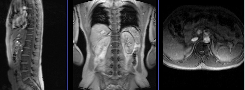
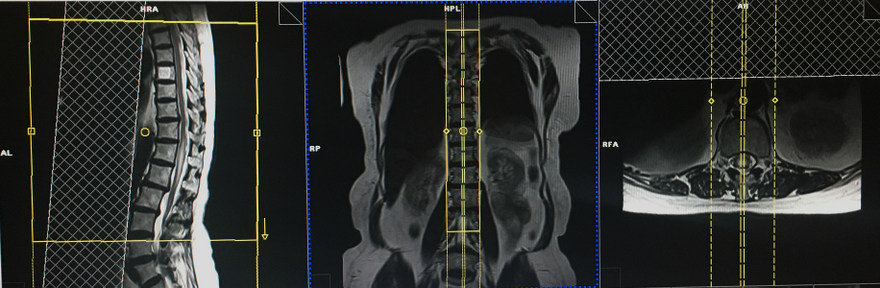
Plan the sagittal slices on the coronal plane and angle the positioning block parallel to the spinal cord. Check the positioning block in the other two planes as well. An appropriate angle must be determined in the axial plane; it should be parallel to the imaginary line running through the center of the vertebral body and the spinous process. Verify the positioning block in the sagittal plane, ensuring that the field of view (FOV) is large enough to cover the lower spinal cord from T4 down to L3. Normally, an FOV of 270-280mm should be sufficient. The slices should adequately cover the spinal cord from side to side.
In the sagittal plane, place a saturation band over the abdomen in front of the aorta to prevent peristalsis and breathing artifacts. The phase direction should be from head to foot to minimize motion artifacts from the abdomen.
Parameters
TR 3000-4000 | TE 100-120 | SLICE 2 MM | FLIP 130-150 | PHASE H>F | MATRIX 320X320 | FOV 270-280 | GAP 10% | NEX(AVRAGE) 4 |
It is important to have some overlap of the spinal cord to avoid missing any anatomy. For example, if the upper sagittal sequences cover the spinal cord from the pons down to T5, then the lower sagittal sequences must cover the spinal cord from T4 down to L3.

T1 tse sagittal 2mm 270-280 FOV or Isotropic 3D T1 .9mm
Plan the sagittal slices on the coronal plane and angle the positioning block parallel to the spinal cord. Check the positioning block in the other two planes as well. An appropriate angle must be determined in the axial plane; it should be parallel to the imaginary line running through the center of the vertebral body and the spinous process. Verify the positioning block in the sagittal plane, ensuring that the field of view (FOV) is large enough to cover the lower spinal cord from T4 down to L3. Normally, an FOV of 270-280mm should be sufficient. The slices should adequately cover the spinal cord from side to side.
In the sagittal plane, place a saturation band over the abdomen in front of the aorta to prevent peristalsis and breathing artifacts. The phase direction should be from head to foot to minimize motion artifacts from the abdomen.

Parameters
TR 400-600 | TE 15-25 | SLICE 2 MM | FLIP 150 | PHASE H>F | MATRIX 320X320 | FOV 270-280 | GAP 10% | NEX(AVRAGE) 4 |
Axial scans are only performed for spinal cord pathologies, such as MS lesions. Axial scanning can be avoided in the lower sagittal sequences if no pathologies are identified.
CLICK THE SEQUENCES BELOW TO CHECK THE SCANS
- localize_3plane1
- T2_tse_tra 3mm2
- T2_flair_tra 3mm3
- T1_axial_3mm4
- Flair_sagittal_3mm5
- Dwi_epi3trace_tra6
- localize C-T spine_3plane7
- T2_sagittal_large FOV8
- T2_sagittal_2mm_SFOV9
- T1_sagittal_2mm_SFOV10
- T2_axial_3mm_SFOV11
- T1_axial_3mm_SFOV12
- localize T-L spine_3plane13
- T2_sagittal_2mm_SFOV14
- T1_sagittal_2mm_SFOV15
-
CONTRAST ENHANCEMENT

- T1_axial_3mm brain16
- T1_sagittal_fat sat_post gd_2mm17
- T1_axial_fat sat_post gd_2mm18
- T1_sagittal_fat sat_post gd_2mm19