Cervical Spine CSF Leak Protocol and Planning
Cerebrospinal Fluid (CSF) Leak
A cerebrospinal fluid (CSF) leak occurs when there is a tear or hole in the dura mater, the outermost layer of the meninges that surrounds the brain and spinal cord, allowing the fluid that cushions these structures to escape. This leakage can result from various causes, including trauma, surgical complications, or spontaneous dural tears. CSF leaks can occur at different levels of the spine or around the skull.
Indications for mri Cervical Spine CSF Leak scan
- History of recent trauma or surgery involving the cervical spine
- Suspected or confirmed cerebrospinal fluid (CSF) leak
Contraindications
- Any electrically, magnetically or mechanically activated implant (e.g. cardiac pacemaker, insulin pump biostimulator, neurostimulator, cochlear implant, and hearing aids)
- Intracranial aneurysm clips (unless made of titanium)
- Pregnancy (risk vs benefit ratio to be assessed)
- Ferromagnetic surgical clips or staples
- Metallic foreign body in the eye
- Metal shrapnel or bullet
Patient preparation
- A satisfactory written consent form must be taken from the patient before entering the scanner room
- Ask the patient to remove all metal objects including keys, coins, wallet, cards with magnetic strips, jewellery, hearing aid and hairpins
- If possible provide a chaperone for claustrophobic patients (e.g. relative or staff )
- Contrast injection risk and benefits must be explained to the patient before the scan
- Gadolinium should only be given to the patient if GFR is > 30
- Offer earplugs or headphones, possibly with music for extra comfort
- Explain the procedure to the patient
- Instruct the patient to keep still
- Note the weight of the patient
Positioning
- Head first supine
- Position the head in the head and neck coil and immobilise with cushions
- Give cushions under the legs for extra comfort
- Centre the laser beam localiser over the mid neck (2.5cm below the chin in chin-down position)

Recommended CSF Leak Protocol and Planning
localiser
A three-plane localizer must be taken at the beginning to localize and plan the sequences. Localizers are normally less than 25 seconds, and they consist of T2\T1 weighted low-resolution scans.
T2 SPACE 3D sagittal 0.7 mm isotropic with high TE
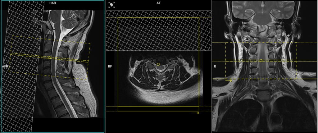
Plan the sagittal 3D block on the coronal localizer, angling the positioning block parallel to the spinal cord. Verify the positioning block in the other two planes. In the axial plane, ensure the block is angled appropriately, parallel to the line running through the center of the vertebral body along the length of the spinous process. Check the positioning block in the sagittal plane to ensure the field of view (FOV) is large enough to cover the entire cervical spine, from the pons down to T2 (typically 250mm). The slices should sufficiently cover the spine from the lateral border of the right transverse process to the lateral border of the left transverse process. Place a saturation band over the neck (in front of the esophagus) in the sagittal plane to avoid swallowing and pulsation artifacts over the spinal area. The phase direction should be head to foot to prevent motion artifacts from the neck.
Note: This 3D sequence is acquired with a TE of 250-350ms. This high TE highlights the CSF and suppresses the background, which is beneficial for identifying a CSF leak.

Parameters
TR 1500-2000 | TE 250-350 | SLICE 0.7 MM | FLIP 120-150 | PHASE H>F | MATRIX 320X320 | FOV 250-260 | GAP 20% | NEX(AVRAGE) 1.4 |
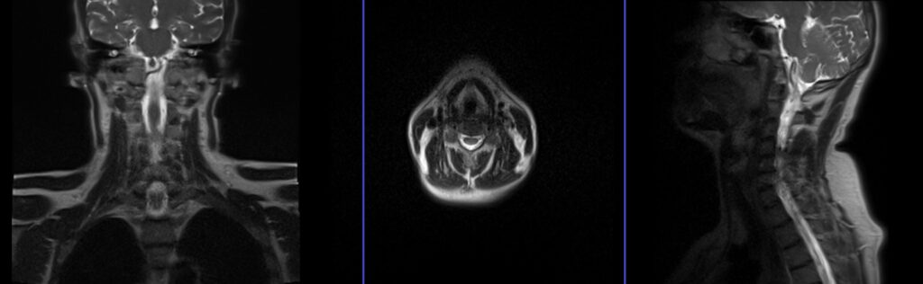
3D SPACE sagittal Images


T2 tse sagittal 3mm
Plan the sagittal slices on the coronal localizer, angling the positioning block parallel to the spinal cord. Verify the positioning block in the other two planes. In the axial plane, ensure the block is angled appropriately, parallel to the line running through the center of the vertebral body along the length of the spinous process. Check the positioning block in the sagittal plane to ensure the field of view (FOV) is large enough to cover the entire cervical spine, from the pons down to T2 (typically 250mm). The slices should sufficiently cover the spine from the lateral border of the right transverse process to the lateral border of the left transverse process. Place a saturation band over the neck (in front of the esophagus) in the sagittal plane to avoid swallowing and pulsation artifacts over the spinal area. The phase direction should be head to foot to prevent motion artifacts from the neck.

Parameters
TR 3000-4000 | TE 100-120 | SLICE 3 MM | FLIP 130-150 | PHASE H>F | MATRIX 320X320 | FOV 250-260 | GAP 10% | NEX(AVRAGE) 2 |
STIR sagittal 3mm
Plan the sagittal slices on the coronal localizer, angling the positioning block parallel to the spinal cord. Verify the positioning block in the other two planes. In the axial plane, ensure the block is angled appropriately, parallel to the line running through the center of the vertebral body along the length of the spinous process. Check the positioning block in the sagittal plane to ensure the field of view (FOV) is large enough to cover the entire cervical spine, from the pons down to T2 (typically 250mm). The slices should sufficiently cover the spine from the lateral border of the right transverse process to the lateral border of the left transverse process. Place a saturation band over the neck (in front of the esophagus) in the sagittal plane to avoid swallowing and pulsation artifacts over the spinal area. The phase direction should be head to foot to prevent motion artifacts from the neck.
Parameters
TR 7000-9000 | TE 110 | FLIP 150 | NEX 2 | SLICE 3 MM | MATRIX 320X256 | FOV 250 | PHASE H>F | GAP 10% | TI 150 |
T1 TSE sagittal 3mm
Plan the sagittal slices on the coronal localizer, angling the positioning block parallel to the spinal cord. Verify the positioning block in the other two planes. In the axial plane, ensure the block is angled appropriately, parallel to the line running through the center of the vertebral body along the length of the spinous process. Check the positioning block in the sagittal plane to ensure the field of view (FOV) is large enough to cover the entire cervical spine, from the pons down to T2 (typically 250mm). The slices should sufficiently cover the spine from the lateral border of the right transverse process to the lateral border of the left transverse process. Place a saturation band over the neck (in front of the esophagus) in the sagittal plane to avoid swallowing and pulsation artifacts over the spinal area. The phase direction should be head to foot to prevent motion artifacts from the neck.
Parameters
TR 400-600 | TE 15-25 | SLICE 3 MM | FLIP 150 | PHASE H>F | MATRIX 320X320 | FOV 250-260 | GAP 10% | NEX(AVRAGE) 2 |
T2 SPACE 3D sagittal 0.7 mm isotropic with high TE at the area of interest
Plan the axial 3D block on the sagittal plane at the suspected leak area and angle the positioning block perpendicular to the spinal cord. In the coronal plane, ensure the block is angled appropriately, parallel to the intervertebral disc space. The slices should sufficiently cover the area of interest. If unsure, consult the radiologist or cover the entire cervical spine with 1mm slices. Place a saturation band over the neck (in front of the esophagus) in the sagittal plane to avoid swallowing and vascular pulsation artifacts over the spinal area.

Parameters
TR 1500-2000 | TE 250-350 | SLICE 0.7 MM | FLIP 120-150 | PHASE A>P | MATRIX 256X256 | FOV 160-180 | GAP 20% | NEX(AVRAGE) 1.4 |
T1 TSE Axial 3mm
Plan the axial slices on the sagittal plane at the suspected leak area and angle the positioning block perpendicular to the spinal cord. In the coronal plane, ensure the block is angled appropriately, parallel to the intervertebral disc space. The slices should sufficiently cover the area of interest. If unsure, consult the radiologist or cover the entire cervical spine with 1mm slices. Place a saturation band over the neck (in front of the esophagus) in the sagittal plane to avoid swallowing and vascular pulsation artifacts over the spinal area.
Parameters
TR 400-500 | TE 15-20 | FLIP 150 | NEX 2 | SLICE 3 MM | MATRIX 256X256 | FOV 150-180 | PHASE A>P R>L | GAP 10% | oversample 100% |
For contrast enhanced CSF Leak imaging
Additional sequences for CSF flow study
Cerebrospinal fluid (CSF) flow MRI is an imaging technique used to visualize and measure the flow of cerebrospinal fluid within the brain and spinal cord. This advanced MRI method utilizes phase-contrast imaging to capture dynamic flow patterns and quantify the velocity and volume of CSF movement. It is particularly useful for diagnosing conditions like hydrocephalus, Chiari malformations, and spinal CSF leaks.
CSF flow and VENC settings
Normal CSF flow velocities can vary significantly based on the individual, the location measured, and physiological conditions, but general guidelines include:
- Peak systolic velocities range from 5 to 10 cm/s in the cerebral aqueduct.
- VENC settings are often set around 5 to 25 cm/s, depending on the expected velocity of CSF flow in the region of interest.
The ideal method for conducting a CSF flow sequence involves using a VENC scout to identify the optimal flow value. However, radiographers often find it challenging to determine this optimal value. For this reason, we prefer to perform multiple scans with different VENC settings. Since the scan time is very short per sequence, performing multiple VENC scans takes almost the same amount of time as performing the scans with a VENC scout.
Cervical Spine CSF FLOW IN- PLANE SCAN PROTOCOL AND PLANNING
CSF flow in-plane VENC 6cm\sec
Plan the sagittal flow sequence slice on the coronal localizer, angle the positioning block parallel to the mid spinal cord. Verify the positioning block in the other two planes. In the axial plane, ensure the block is appropriately angled, parallel to the line running through the center of the vertebral body along the length of the spinous process. Check the positioning block in the sagittal plane to ensure the field of view (FOV) is large enough to cover the entire cervical spine, from the pons down to T2 (typically 240mm).

Parameters
TR 23.7 | TE 7.78 | FLIP 20 | NEX 1 | SLICE 6MM | MATRIX 256×205 | FOV 180 | PHASE A>P | VELOCITY 6cm\sec | TRIGGER Pulse/Retro |
CSF flow in-plane images


CSF flow in-plane VENC 10cm\sec
Plan the sagittal flow sequence slice on the coronal localizer, angle the positioning block parallel to the mid spinal cord. Verify the positioning block in the other two planes. In the axial plane, ensure the block is appropriately angled, parallel to the line running through the center of the vertebral body along the length of the spinous process. Check the positioning block in the sagittal plane to ensure the field of view (FOV) is large enough to cover the entire cervical spine, from the pons down to T2 (typically 240mm).
Parameters
TR 23.7 | TE 7.78 | FLIP 20 | NEX 1 | SLICE 6MM | MATRIX 256×205 | FOV 180 | PHASE A>P | VELOCITY 10cm\sec | TRIGGER Pulse/Retro |
CSF flow in-plane VENC 15cm\sec
Plan the sagittal flow sequence slice on the coronal localizer, angle the positioning block parallel to the mid spinal cord. Verify the positioning block in the other two planes. In the axial plane, ensure the block is appropriately angled, parallel to the line running through the center of the vertebral body along the length of the spinous process. Check the positioning block in the sagittal plane to ensure the field of view (FOV) is large enough to cover the entire cervical spine, from the pons down to T2 (typically 240mm).
Parameters
TR 23.7 | TE 7.78 | FLIP 20 | NEX 1 | SLICE 6MM | MATRIX 256×205 | FOV 180 | PHASE A>P | VELOCITY 15cm\sec | TRIGGER Pulse/Retro |
CSF flow in-plane VENC 20cm\sec
Plan the sagittal flow sequence slice on the coronal localizer, angle the positioning block parallel to the mid spinal cord. Verify the positioning block in the other two planes. In the axial plane, ensure the block is appropriately angled, parallel to the line running through the center of the vertebral body along the length of the spinous process. Check the positioning block in the sagittal plane to ensure the field of view (FOV) is large enough to cover the entire cervical spine, from the pons down to T2 (typically 240mm).
Parameters
TR 23.7 | TE 7.78 | FLIP 20 | NEX 1 | SLICE 6MM | MATRIX 256×205 | FOV 180 | PHASE A>P | VELOCITY 20cm\sec | TRIGGER Pulse/Retro |
CSF flow through- plane scan protocol and planning
CSF flowthrough- plane VENC 6cm\sec
Plan the axial CSF flow slice on the sagittal plane at the suspected leak area and angle the positioning block perpendicular to the spinal cord. In the coronal plane, ensure the block is angled appropriately, perpendicular to the spinal cord.

Parameters
TR 23.7 | TE 7.78 | FLIP 20 | NEX 1 | SLICE 6MM | MATRIX 256×205 | FOV 180 | PHASE A>P | VELOCITY 6cm\sec | TRIGGER Pulse/Retro |