MRI Prostate (Oblique Imaging)
Indications for prostate mri scan
- Assessment of complications after pelvic surgery
- Prior to biopsy for prostate cancer diagnosis
- Post radiotherapy and chemotherapy assessment
- Newly diagnosed prostate cancer staging
- Diagnosis of recurrent prostate cancer
- Post prostatectomy assessment
- Pre surgical assessment
- Tumor detection and staging
- Congenital abnormalities.
- Enlarged prostate
- Rising PSA
Contraindications
- Any electrically, magnetically or mechanically activated implant (e.g. cardiac pacemaker, insulin pump biostimulator, neurostimulator, cochlear implant, and hearing aids)
- Intracranial aneurysm clips (unless made of titanium)
- Pregnancy (risk vs benefit ratio to be assessed)
- Ferromagnetic surgical clips or staples
- Metallic foreign body in the eye
- Metal shrapnel or bullet
Patient preparation for prostate mri scan
- A satisfactory written consent form must be taken from the patient before entering the scanner room
- Ask the patient to remove all metal objects including keys, coins, wallet, cards with magnetic strips, jewellery, hearing aid and hairpins
- Ask the patient to undress and change into a hospital gown
- Contrast injection risk and benefits must be explained to the before the scan
- Gadolinium should only be given to the patient if GFR is > 30
- An intravenous line must be placed with extension tubing extending out of the magnetic bore
- Claustrophobic patients may be accompanied into the scanner room e.g. by staff member or relative with proper safety screening
- Offer earplug or headphones possibly with music for extra comfort.
- Explain the procedure to the patient and answer questions
- Note the weight of the patient
Positioning for prostate mri scan
- Position the patient in supine position with head pointing towards the magnet (head first supine).
- Position the patient over the spine coil and place the body coils over abdomen and pelvis (nipple down to three inches below symphysis pubis).
- Securely tighten the body coil using straps to prevent respiratory artefacts.
- Give a pillow under the head and cushions under the legs for extra comfort.
- Centre the laser beam localiser over the iliac crest.
- Register the patient in the scanner as head first supine.

Recommended Prostate MRI Protocols and Planning
Prostate mri scan localiser
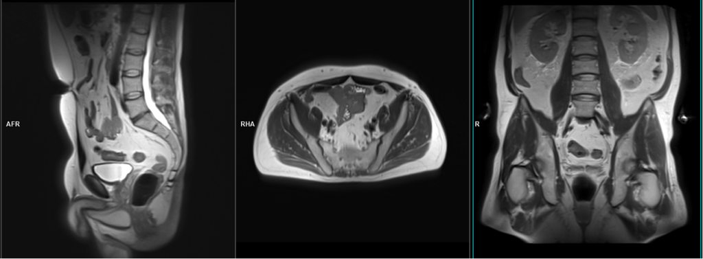
A three-plane HASTE localizer must be taken initially to localize and plan the sequences. These are fast, single-shot localizers with under 25s acquisition time, which are excellent for localizing abdominal and pelvic structures.

T2 tse sagittal 3mm SFOV prostate
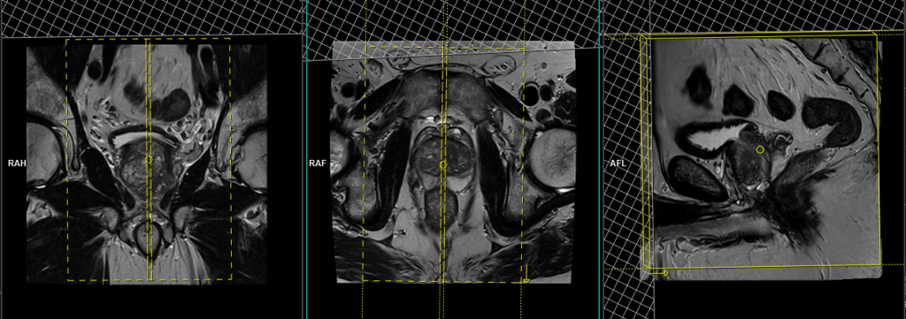
Plan the sagittal slices on the axial plane, angle the positioning block parallel to the interpubic fibrocartilage and the anal canal. Check the positioning block in the other two planes, ensuring an appropriate angle is given in the coronal plane (parallel to the interpubic fibrocartilage). The slices must be sufficient to cover the entire pelvis from the right acetabulum to the left acetabulum. The field of view (FOV) must be large enough to encompass the prostate and seminal vesicles (typically 180mm-200mm). Additionally, to minimize artifacts arising from arterial pulsation, peristalsis, and breathing, consider incorporating saturation bands on the top and front of the sagittal block.

Parameters
TR 4000-5000 | TE 100-120 | SLICE 3 MM | FLIP 130-160 | PHASE A>P | MATRIX 320X320 | FOV 180-200 | GAP 10% | NEX(AVRAGE) 4 |
T2 tse axial oblique 3mm SFOV prostate
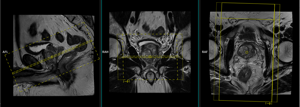
Plan the axial oblique slices on the sagittal plane; angle the positioning block perpendicular to the prostatic urethra (i.e., parallel to the base of the urinary bladder). Check the positioning block in the other two planes. An appropriate angle must be given in the coronal plane (perpendicular to the prostatic urethra). Slices must be sufficient to cover the whole prostate and seminal vesicles. Additionally, to minimize artefacts arising from arterial pulsation, peristalsis, and breathing, consider incorporating saturation bands on top and in front of the axial block.

Parameters
TR 4000-5000 | TE 100-120 | SLICE 3 MM | FLIP 130-160 | PHASE R>L | MATRIX 320X288 | FOV 180-200 | GAP 10% | NEX(AVRAGE) 4 |
T2 tse coronal oblique 3mm SFOV
Plan the coronal oblique slices on the sagittal plane, angle the positioning block parallel to the prostatic urethra (i.e., perpendicular to the base of the urinary bladder). Check the positioning block in the other two planes, ensuring an appropriate angle is given in the axial plane (parallel to the right and left hip joints). The slices must be sufficient to cover the entire prostate and seminal vesicles. Additionally, to minimize artefacts stemming from arterial pulsation and breathing, consider incorporating saturation bands on the top and front of the coronal block.

Parameters
TR 3000-4000 | TE 100-120 | SLICE 3 MM | FLIP 130-150 | PHASE R>L | MATRIX 320X256 | FOV 180-230 | GAP 10% | NEX(AVRAGE) 5 |
ZOOMIT\DWI epi3scan trace axial 3 mm SFOV
Plan the axial DWI oblique slices on the sagittal plane; angle the positioning block perpendicular to the prostatic urethra (i.e., parallel to the base of the urinary bladder). Check the positioning block in the other two planes. An appropriate angle must be given in the coronal plane (perpendicular to the prostatic urethra). Slices must be sufficient to cover the whole prostate and seminal vesicles. Additionally, to minimize artefacts arising from arterial pulsation, peristalsis, and breathing, consider incorporating saturation bands on top and in front of the axial block.

Parameters ZOOIT
TR 5000-6000 | TE 74 | FLIP 130 | NEX 10 | SLICE 3 MM | MATRIX 204X192 | FOV 200X110 | PHASE R>L | GAP 10% | B VALUE 0 |
Parameters EPI DWI
TR 5000-6000 | TE 110 | FLIP 130 | NEX 10 | SLICE 3 MM | MATRIX 192X192 | FOV 200-250 | PHASE R>L | GAP 10% | B VALUE 0 |
Zoomit DWI
Zoomit DWI is an advanced MRI imaging technique that leverages Siemens’ TimTX TrueShape platform and the application called Syngo ZOOMit. TimTX TrueShape introduces a new transmit platform with two independent transmitters, enabling flexible switching of RF waveforms and gradient shapes. This dynamic parallel transmission (pTX) capability opens up new possibilities for imaging applications.
Syngo ZOOMit, the first application based on TimTX TrueShape, utilizes the concept of “zooming” in MR imaging. Similar to optical zoom in a camera, ZOOMit allows for exciting a smaller field-of-view (FOV) than the object in the phase-encoding direction, thereby avoiding aliasing artifacts. By reducing the FOV, fewer phase-encoding lines are required, leading to faster scan times, improved spatial resolution in the region of interest, and reduced motion and flow artifacts.
Zoomit DWI offers several advantages over conventional DWI techniques. It employs multiple parallel radiofrequency pulse sequences simultaneously, capturing high signal specifically from the area of interest. This approach reduces folding artifacts, provides better anatomical detail, decreases distortion and blurring, and improves overall image quality. Additionally, it allows for faster screening, increased spatial resolution, and minimized susceptibility artifacts and geometric distortions.
With ZOOMit, radiologists and radiographers can selectively image the volume of interest, achieve faster and higher-resolution imaging, enhance diagnostic confidence by detecting and evaluating smaller lesions in challenging areas, and broaden the scope of clinical MR imaging.

T2 stir coronal 5 mm Large FOV
Plan the big FOV coronal slices on the sagittal plane; angle the position block parallel to the lumbar spine. Check the positioning block in the other two planes. An appropriate angle must be given in the axial plane (parallel to the line from right to left hip joint). Slices must be sufficient to cover the para aortic area from mid abdomen to the sacrum. FOV must be big enough to cover the abdoman and pelvis (normally 380mm-400mm). Big FOV scans are normally taken to check the Para-aortic and pre-sacral nodes.

Parameters
TR 4000-5000 | TE 110 | FLIP 130 | NEX 2 | SLICE 5MM | MATRIX 384X384 | FOV 380-400 | PHASE R>L | GAP 10% | TI 150 |
T1 tse axial 6 mm Large FOV
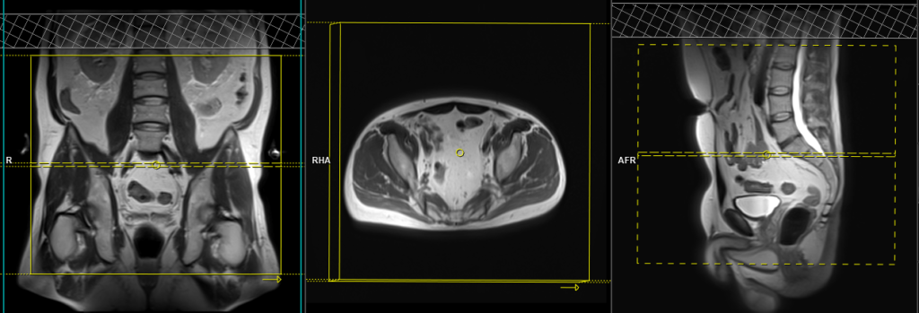
Plan the large FOV coronal slices on the sagittal plane, angle the positioning block vertically across the abdomen and pelvis. Verify the positioning block in the other two planes. Ensure an appropriate angle is given in the axial plane (parallel to the line from the right to the left hip joint). The slices must sufficiently cover the abdomen and pelvis from the anterior abdominal wall to the sacrum. The FOV should be big enough to encompass the abdomen and pelvis (normally ranging from 380mm to 400mm). Large FOV scans are commonly performed to assess the local spread of diseases and to evaluate the para-aortic and pre-sacral nodes.

Parameters
TR 400-600 | TE 15-25 | SLICE 6 MM | FLIP 160 | PHASE R>L | MATRIX 512X384 | FOV 350-400 | GAP 10% | NEX(AVRAGE) 2 |
FOR Post Contrast IMAGING
Most common indications for contrast enhanced pelvis scans
- Post radiotherapy and chemotherapy assessment
- MRI prior to biopsy for prostate cancer assessment
- Pre surgical assessment
- Infection (prostatitis) or prostate abscess
- Post prostatectomy assessment
T1 TWIST DIXON\T1 VIBE 3D fat sat axial dynamic 4 pre 22 post
Plan the axial TWIST 3D block on the sagittal plane; angle the positioning block perpendicular to the prostatic urethra (i.e., parallel to the base of the urinary bladder). Check the positioning block in the other two planes. An appropriate angle must be given in the coronal plane (perpendicular to the prostatic urethra). Slices must be sufficient to cover the whole prostate and seminal vesicles. Additionally, to minimize artefacts arising from arterial pulsation, peristalsis, and breathing, consider incorporating saturation bands on top and in front of the axial block. Ensure an adequate amount of slices and phase oversampling are utilized to prevent wrap-around artifacts.

A dynamic VIBE DIXON dynamic sequence consists of 26 3mm 3D scans. Contrast injection must be administered after the fourth dynamic sequence.
Parameters TWIST DIXON
TR 4-5 | TE 1.25 2.49 | FLIP 14 | NEX 1 | SLICE 3MM | MATRIX 204X192 | FOV 180-200 | PHASE R>L | DYNAMIC 26 SCAN | IPAT ON |
Parameters FLASH 3D
TR 4-5 | TE 2 | FLIP 12 | NEX 1 | SLICE 3MM | MATRIX 256X192 | FOV 180-200 | PHASE A>P | DYNAMIC 11 SCAN | IPAT ON |
Optional Scans
T1 tse fat sat axial 3mm SFOV
Plan the axial slices on the sagittal plane and angle the position block perpendicular to the urethra (i.e., parallel to the base of the urinary bladder). An appropriate angle must be given in the coronal plane, parallel to the line between the right and left hip joints. Slices should sufficiently cover the pelvis from the middle of the urinary bladder down to the penile shaft. Adding saturation bands on the top and front of the axial block will reduce artifacts from arterial pulsation and breathing. T1 fat sat post-contrast scans are only used in post-prostatectomy patients.

Parameters
TR 400-600 | TE 15-25 | SLICE 3 MM | FLIP 130 | PHASE R>L | MATRIX 256X256 | FOV 180-230 | GAP 10% | NEX(AVRAGE) 5 |
CLICK THE SEQUENCES BELOW TO CHECK THE SCANS
- Localizer_3 plane1
- T2_TSE_SAGITTAL_SFOV2
- T2_TSE_AXIAL_BIG-FOV_WHOLE PELVIS3
- T1_TSE_AXIAL_BIG FOV_WHOLE PELVIS4
- T2_STIR_CORONAL_BIG FOV5
- T2_TSE_AXIAL_OBLIQUE_SFOV6
- T2_TSE_CORONAL_OBLIQUE_SFOV7
- DWI_EPI_3TRACE_AXIAL OBLIQUE8
- T1_VIBE 3D_DYNAMIC_AXIAL_1PRE_POST9
- OPTIONAL FOR PROSTATECTOMY PATIENTS

- T1_TSE_AXIAL_FAT-SAT_ONLY FOR prostatectomy patients10
