MRI Hip Arthrogram Protocol and Planning
Indications for MRI hip arthrogram
- For the evaluation of foreign bodies in the acetabular fossa
- For the evaluation of cystic changes in the acetabulum
- For the evaluation of hip dysplasia in children
- For the evaluation of osteochondromatosis
- For the evaluation of focal chondropathy
- For the evaluation of labrum lesions
- For the evaluation of labral tear
Contraindications
- Any electrically, magnetically or mechanically activated implant (e.g. cardiac pacemaker, insulin pump biostimulator, neurostimulator, cochlear implant, and hearing aids)
- Intracranial aneurysm clips (unless made of titanium)
- Pregnancy (risk vs benefit ratio to be assessed)
- Ferromagnetic surgical clips or staples
- Metallic foreign body in the eye
- Metal shrapnel or bullet
Patient preparation for MRI Hip Arthrogram
- A satisfactory written consent form must be taken from the patient before entering the scanner room
- Ask the patient to remove all metal object including keys, coins, wallet, any cards with magnetic strips, jewellery, hearing aid and hairpins
- If possible provide a chaperone for claustrophobic patients (e.g. relative or staff )
- Contrast injection risk and benefits must be explained to the patient before the scan
- Offer earplugs or headphones, possibly with music for extra comfort
- Explain the procedure to the patient
- Instruct the patient to keep still
- Note the weight of the patient
Positioning pre arthrogram
- Position the patient in supine position with head pointing towards the magnet (head first supine) Now give slight internal rotation of the hip
- Position the patient over the spine coil and place the body coil over the pelvis(iliac crest down to mid thigh)
- Securely tighten the body coil using straps to prevent respiratory artefacts
- Give a pillow under the head for extra comfort (do not give cushions under the legs )
- Centre the laser beam localiser over hip joints (4 inches below iliac crest)

Recommended HIP Pre Arthrogram Protocols and Planning
localizer pre arthrogram
A three-plane localizer must be taken at the beginning to localize and plan the sequences. Localizers are normally less than 25 seconds, T1-weighted low-resolution scans.
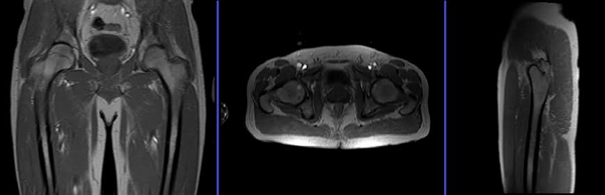
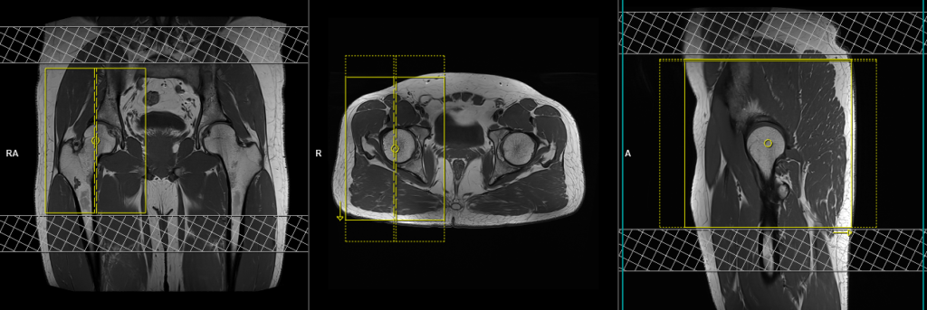
T2 stir coronal 3mm pre arthrogram
Plan the coronal slices on the axial plane; angle the positioning block parallel to the RT and LT femoral heads. Check the positioning block in the other two planes. An appropriate angle must be given in the sagittal plane (parallel to the femur). The slices should adequately encompass the hip joints, starting from the ischial tuberosities and extending up to the line of pubic symphysis. To minimize ghosting artifacts caused by peristalsis and breathing, consider using a saturation band over the coronal block.

Parameters
TR 4000-5000 | TE 110 | FLIP 130 | NEX 2 | SLICE 3 MM | MATRIX 320X320 | FOV 350-380 | PHASE R>L | GAP 10% | TI 130 |
T1 tse axial 3mm pre arthrogram
Plan the axial slices on the coronal plane and angle the positioning block parallel to both the right and left femoral heads. Check the positioning block in the other two planes. Ensure an appropriate angle is maintained in the sagittal plane, which should be perpendicular to the femur. The slices must be sufficient to cover the hip joints from the anterior superior iliac spine to 1 inch below the lesser trochanter. To minimize ghosting artifacts caused by peristalsis and breathing, consider using a saturation band over the axial block.

Parameters
TR 400-600 | TE 15-25 | SLICE 3 MM | FLIP 90 | PHASE R>L | MATRIX 320X320 | FOV 340-360 | GAP 10% | NEX(AVRAGE) 2 |
Arthrography
An arthrogram is a diagnostic procedure used to examine joint capsule conditions. During this interventional process, a radiologist injects contrast medium into the joint space to assess any abnormalities. For MRI hip arthrograms, the injections are typically administered with X-ray fluoroscopic guidance, although some radiologists may opt for ultrasound guidance.
Positioning for injection:- Proper hip positioning plays a vital role in performing an arthrogram. Begin by placing the patient in a supine position with the hip internally rotated. Partially flex the knees and provide support by placing a pillow under the knee. To immobilize the leg, use sandbags over the ankle joint.
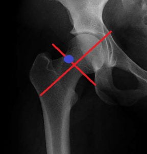
Marking for injection:- When marking the injection site, it is crucial to steer clear of the iliopsoas tendon and femoral artery.

Using fluoroscopic guidance, create an imaginary line that divides the femoral head and neck equally. Then, draw a second line perpendicular to the first one. Identify a point slightly above the intersection of the two lines at the junction of the femoral head and neck and mark it using a marking pen.
Injection: – Only a trained radiologist should perform the injection. Radiographers should only assist with the preparation. The following instructions are intended for a trained person authorized to perform joint injections.
Begin by cleansing the designated site using betadine. Subsequently, administer local anesthesia to the skin and subcutaneous tissues using 1% lidocaine.
Typically, a 22 G 3½” needle is used for all MR arthrogram injections.
Now place the tip of the needle directly onto the marked spot, then check under fluoroscopic guidance to confirm intra-articular needle placement.
Proceed to inject 10 to 15cc of diluted Magnevist.
Positioning post joint injection
- Position the patient in supine position with head pointing towards the magnet (head first supine) Now give slight internal rotation of the hip
- Position the patient over the spine coil and place the body coil over the pelvis(iliac crest down to mid thigh)
- Securely tighten the body coil using straps to prevent respiratory artefacts
- Give a pillow under the head for extra comfort (do not give cushions under the legs )
- Centre the laser beam localiser over hip joints (4 inches below iliac crest)
Recommended MRI Hip Arthrogram Protocols and Planning
localizer unilateral
A three-plane localizer must be taken at the beginning to localize and plan the sequences. Localizers are normally less than 25 seconds, T1-weighted low-resolution scans.

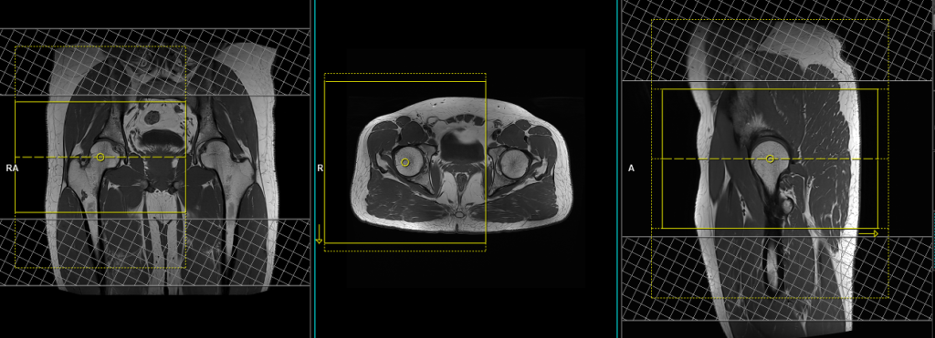
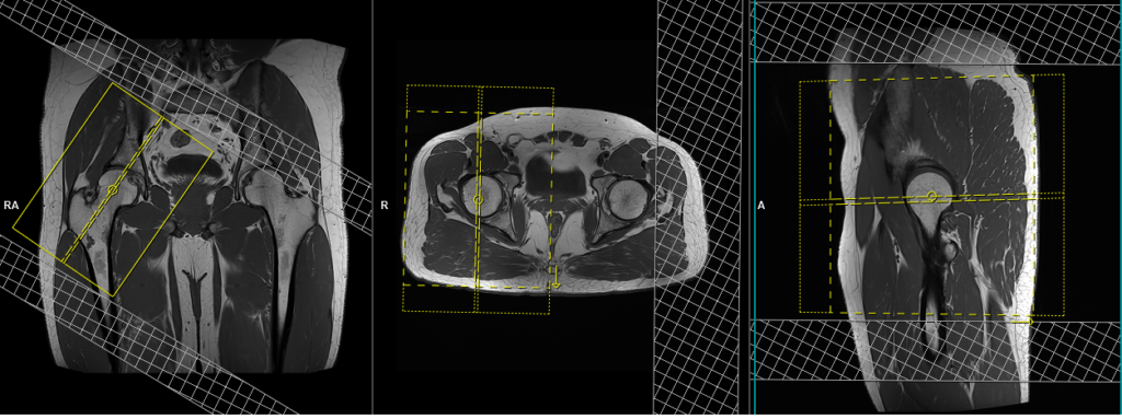
T1 vibe 3d DIXON coronal 0.9mm small FOV
Plan the coronal 3D block on the axial plane. Angle the positioning block perpendicular to the acetabulum (i.e., parallel to the femoral head and neck). Check the positioning block in the other two planes. An appropriate angle must be given in the sagittal plane (perpendicular to the acetabulum). The slices should adequately encompass the hip joint, starting from the ischial tuberosities and extending up to the line of the pubic symphysis. To minimize ghosting artifacts resulting from peristalsis, vascular pulsation, and breathing, consider incorporating a saturation band at the top and bottom of the coronal block.

Parameters
TR 6-7 | TE 2.39 4.77 | SLICE .9 MM | FLIP 12 | PHASE R>L | MATRIX 224X224 | FOV 180-220 | GAP 10% | NEX(AVRAGE) 2 |
T1 vibe 3d DIXON AXIAL 0.9mm small FOV
Plan the axial 3D block on the coronal plane and angle the positioning block horizontally across the femoral heads. Check the positioning block in the other two planes to ensure an appropriate angle is maintained in the sagittal plane, which should be perpendicular to the femur. The slices must be sufficient to cover the hip joints from 1 inch above the anterior inferior iliac spine to 1 inch below the lesser trochanter. To minimize ghosting artifacts resulting from peristalsis, vascular pulsation, and breathing, consider incorporating a saturation band at the top and bottom of the axial block.
Parameters
TR 6-7 | TE 2.39 4.77 | SLICE .9 MM | FLIP 12 | PHASE A>P | MATRIX 224X224 | FOV 180-220 | GAP 10% | NEX(AVRAGE) 2 |
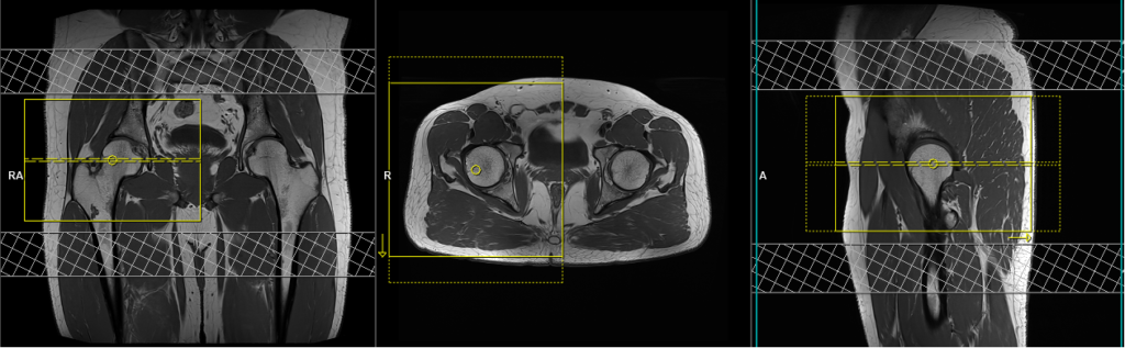
T1 tse fat sat axial 3mm SFOV
Plan the axial slices on the coronal plane and angle the positioning block horizontally across the femoral heads. Check the positioning block in the other two planes to ensure an appropriate angle is maintained in the sagittal plane, which should be perpendicular to the femur. The slices must be sufficient to cover the hip joints from 1 inch above the anterior inferior iliac spine to 1 inch below the lesser trochanter. To minimize ghosting artifacts resulting from peristalsis, vascular pulsation, and breathing, consider incorporating a saturation band at the top and bottom of the axial block.
Parameters
TR 400-600 | TE 15-20 | FLIP 150 | NEX 3 | SLICE 3 MM | MATRIX 256X256 | FOV 180 | PHASE A>P | OVERSAMPLE 100% | FAT SAT SPAIR |
T1 tse fat sat sagittal 3mm SFOV
Plan the sagittal slices on the coronal plane; angle the position block parallel to the femur. Check the positioning block in the other two planes. An appropriate angle must be given in the axial plane (perpendicular to the femoral head). Slices must be sufficient to cover the hip joint from outer cortex of the greater trochanter up to the inner portion of the acetabulum. To minimize ghosting artifacts caused by peristalsis and breathing, consider using a saturation band over the axial block.
Parameters
TR 400-600 | TE 15-20 | FLIP 150 | NEX 3 | SLICE 3 MM | MATRIX 256X256 | FOV 180 | PHASE A>P | OVERSAMPLE 100% | FAT SAT SPAIR |
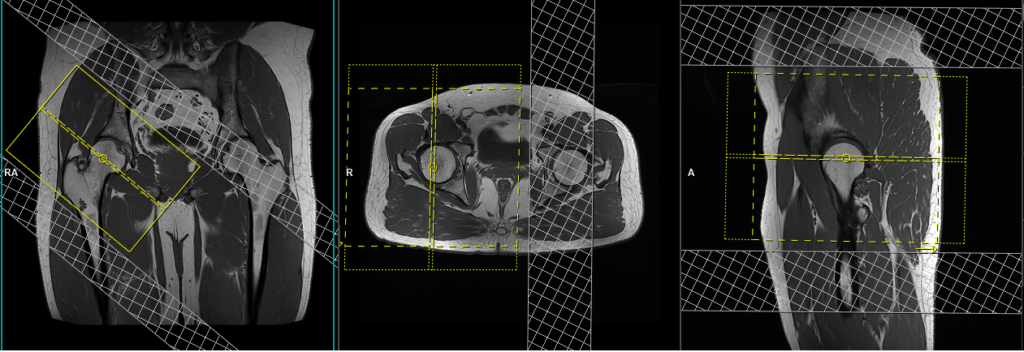
T1 axial oblique 3mm SFOV
Plan the axial oblique slices on the coronal plane, angling the positioning block parallel to the femoral neck. Verify the positioning block alignment in the other two planes. Ensure an appropriate angle is established in the axial plane, perpendicular to the femoral head. The slices should adequately cover the hip joint, spanning one inch above the superior border of the acetabulum to one inch below the inferior border of the acetabulum. To minimize ghosting artifacts caused by peristalsis and breathing, consider using a saturation band over the axial oblique block.
Parameters
TR 400-600 | TE 15-20 | FLIP 150 | NEX 3 | SLICE 3 MM | MATRIX 256X256 | FOV 180 | PHASE A>P | OVERSAMPLE 100% | FAT SAT OFF |
Optional Scans
T1 TSE FAT SAT sagittal oblique 3mm SFOV
Plan the sagittal oblique slices on the coronal plane; angle the positioning block perpendicular to the femoral neck. Check the positioning block in the other two planes. Ensure an appropriate angle is set in the axial plane (perpendicular to the femoral head). The slices should sufficiently cover the hip joint, extending one inch above the acetabulum to one inch below the greater trochanter. To minimize ghosting artifacts caused by peristalsis and breathing, consider using a saturation band over the sagittal oblique block.
Parameters
TR 400-600 | TE 15-20 | FLIP 150 | NEX 3 | SLICE 3 MM | MATRIX 256X256 | FOV 180 | PHASE A>P | OVERSAMPLE 100% | FAT SAT SPAIR |