MRI Myocardial Mapping(T1,T2 & T2* mapping)
Myocardial Mapping
Myocardial mapping, a groundbreaking diagnostic technique, has emerged as a pivotal tool in the evaluation of cardiac conditions. By providing valuable insights into tissue characteristics and functionality, it plays a crucial role in diagnosing and managing heart diseases. Three key techniques – T1 mapping, T2 mapping, and T2* mapping – are at the forefront of this innovative approach.
T1 Mapping: T1 mapping allows clinicians to gauge myocardial tissue properties, helping in the early detection of conditions like myocardial fibrosis, inflammation, or edema. It quantifies the rate at which the heart muscle relaxes after a radiofrequency pulse, offering a nuanced understanding of tissue health.
T2 Mapping: When it comes to detecting myocardial edema or inflammation, T2 mapping takes center stage. This technique measures the transverse relaxation time of tissues, effectively highlighting areas with elevated water content, a hallmark of certain heart conditions.
T2* Mapping: Particularly relevant in cases of iron overload, T2* mapping identifies areas of the heart where iron deposits may lead to cardiomyopathy or other cardiac complications. It allows for early intervention to prevent severe health consequences.
Native T1 mapping

T2 mapping

T2 star mapping

Indications for cardiac T1,T2 & T2* mapping
- Heart failure and unexplained troponin elevation
- Suspected myocardial disease and masses
- Congenital heart disease
- Cardiac amyloidosis
- Inflammation or edema
- Myocardial fibrosis
- Heart iron deposits
- Cardiomyopathy
- Myocarditis
Contraindications
- Any electrically, magnetically or mechanically activated implant (e.g. cardiac pacemaker, insulin pump biostimulator, neurostimulator, cochlear implant, and hearing aids)
- Intracranial aneurysm clips (unless made of titanium)
- Pregnancy (risk vs benefit ratio to be assessed)
- Ferromagnetic surgical clips or staples
- Metallic foreign body in the eye
- Metal shrapnel or bullet
Patient preparation for MRI Myocardial Mapping
- A satisfactory written consent form must be taken from the patient before entering the scanner room
- Ask the patient to remove all metal objects including keys, coins, wallet, cards with magnetic strips, jewellery, hearing aid and hairpins
- Ask the patient to undress and change into a hospital gown
- Instruct the patient to hold their breath for the breath hold scans and breathe gently for the gated scans (its advisable to coach the patient two to three times before starting the scan)
- Request the patient to use the rest room before procedure
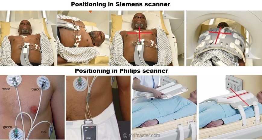
- Follow the appropriate manufacturer’s instructions for the ECG electrodes and the blue tooth receiver placement
- If the chest is covered with hair it is necessary to shave the required area before placing the ECG electrodes
- Thoroughly clean the ECG contact area with an abrasive gel
- Claustrophobic patients may be accompanied into the scanner room e.g. by staff member or relative with proper safety screening
- Offer headphones for communicating with the patient and ear protection
- Explain the procedure to the patient and answer questions
- Note the weight of the patient
Positioning for MRI Myocardial Mapping
- Position the patient in a supine position with head pointing towards the magnet (head first supine)
- Position the patient over the spine coil and connect the ECG electrodes as specified above and in accordance with the specific manufacturer’s instructions
- Check the quality of the ECG in the integrated ECG display on the scanner terminal. If the signal is not satisfactory and consistent, change the location of the electrodes
- Place the body coil or the dedicated cardiac coil over the chest
- Securely tighten the coil using straps to prevent respiratory artefacts
- Give cushions under the head and legs for extra comfort
- Centre the laser beam localiser over mid chest (i.e. over the nipples)
T1 Mapping
T1 mapping is a valuable method that utilizes the T1 relaxation time of various tissues to detect and characterize different pathological conditions within the myocardium. T1 relaxation time, also known as longitudinal relaxation time, represents the duration it takes for a nucleus to return to thermodynamic equilibrium along the B0 magnetic field direction. The specific T1 value of a tissue depends on how quickly the excited protons release their energy to the surrounding environment. These T1 values are influenced by factors such as molecular size, shape, viscosity, temperature, and the strength of the magnetic field.
To ensure precise myocardial T1 mapping, it’s crucial to establish normal T1 values for healthy myocardial tissue using the particular MRI scanner being employed for mapping. In our department, we accomplished this by scanning 30 healthy volunteers. We employed a modified Look-Locker inversion recovery (MOLLI) mapping technique to identify native T1 values for normal tissues. The typical myocardial T1 values we obtained on our 1.5 Tesla scanner were approximately 930 ± 20 ms, and on a 3 Tesla scanner, they were approximately 1065 ± 20 ms. It’s worth noting that native T1 values can exhibit variations based on factors like age and gender. Pathological processes often disrupt the water composition or local molecular environment of tissues, leading to deviations from normal T1 values. To visualize these variations, mapping techniques use color-coded maps to differentiate between normal myocardium and pathological conditions.
T1 mapping utilizes an inversion recovery technique to measure T1 relaxation times at multiple time points after an initial preparation pulse. There are three primary types of T1 mapping techniques: Look-Locker (LL), Modified Look-Locker Sequence (MOLLI), and Saturation Recovery Single-Shot Acquisition (SASHA). The most commonly used T1 mapping sequence is the Modified Look-Locker sequence (MOLLI).
Look-Locker (LL): The Look-Locker technique acquires multiple images along the recovery curve with several specific inversion time (TI) values measured after the initial inversion pulse. However, this technique has limitations, as the heart is at a different phase of the cardiac cycle in each image, leading to inaccurate T1 mapping due to significant in-plane and through-plane motion artifacts. Consequently, it has been mostly replaced by more modern techniques.
Modified Look-Locker Sequence (MOLLI): Modified Look-Locker (MOLLI) is a modern technique developed to overcome the limitations of the Look-Locker technique. MOLLI acquires single-shot images intermittently during diastole over 3 to 5 heartbeats after the inversion pulse.
Recommended Native T1 mapping Protocols and Planning
Localiser
An initial three-plane SSFP (TrueFISP, B-FFE, or FIESTA) localizer scan is required for localization and sequence planning. These fast single-shot localizers have an acquisition time of under 25 seconds, making them excellent for localizing chest structures.
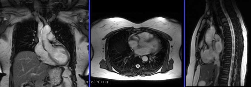
Cardiac MRI planning localiser
Plan the axial localizer on the coronal plane and position the block across the chest as shown. The slices must cover the entire heart from the aortic arch to the diaphragm (usually 3-4 slices). Check the position in the other two planes.
Plan the sagittal localizer on the coronal plane and position the block parallel to the chest as demonstrated. The slices should encompass the entire heart from right to left (usually 3-4 slices). Verify the position in the other two planes.
Plan the coronal localizer on the axial plane and position the block across the chest as indicated. The slices must encompass the entire heart from the sternum to the thoracic aorta (usually 3-4 slices). Confirm the position in the other two planes.
All three blocks must be ISO-centered within the magnetic bore to avoid any inhomogeneity artifacts. These localizers are performed using a combination of ECG gating and breath-holding. Scans should be conducted during an expiratory breath-hold with an ECG trigger for every heartbeat (In our department, we instruct patients to take two breaths in and out before giving the “breathe out and hold” instruction).

T2 TRUE FISP Bight blood axial
Plan the axial T2 scans on the coronal localizer. Plan the planning block straight across the chest, as shown. Verify the positioning in the other two planes. An appropriate angle must be established in the sagittal plane (perpendicular to the thoracic spine). The number of slices should be sufficient to cover the heart from the aortic arch to the apex (usually 18-20 slices). These axial slices are acquired using a combination of ECG gating and breath-holds. Scans should be performed under expiratory breath-holds, with ECG triggers set for every second heartbeat. Axial bright blood scans involve a multiple breath-hold technique that acquires 8-10 slices with each breath hold. In our department, the cardiologist prefers conducting bright blood axials.

Recommended Protocol
TR 278 | TE 1.14 | FLIP 80 | NEX 1 | SLICE 8MM | MATRIX 224×224 | FOV 360 | PHASE A>P | OS NO | TRIGGER YES |
Two chamber localiser
Plan the 2-chamber localizer on the axial plane and angle the planning block parallel to the interventricular septum. Move the position block to the center of the left ventricle, aligning it with the line along the center of the mitral valve and left ventricular apex. (Note: In most patients, these structures may not be visible in the same image; scroll through the axial images to identify both structures.) Verify the position in the other two planes. Provide an appropriate angle in the sagittal plane to maintain parallel alignment with the interventricular septum. This single-slice (non-cine) 2-chamber localizer is performed using a combination of ECG gating and breath-holding. Scans should be conducted during expiration breath-holds with an ECG trigger set for every heartbeat.

Short axis localiser
Plan the short-axis localizer using the 2-chamber view as a reference, and orient the planning block perpendicular to the line running along the center of the mitral valve and the left ventricular apex, essentially perpendicular to the long axis of the left ventricle. Confirm the positioning in the other two planes as well. Provide an appropriate angle for the axial plane, which is perpendicular to the interventricular septum. Acquire slices that adequately cover the heart from the middle of the left atrium to the left ventricular apex; typically, 8-10 slices are needed. This multi-slice, non-cine short-axis localizer is conducted using a combination of ECG gating and breath-holding. Perform scans during expiration with breath-holding, triggering the ECG with each heartbeat.

Four chamber cine
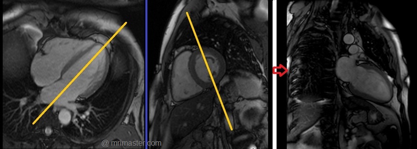
Plan the 4-chamber cine on the 2-chamber localizer and angle the planning block parallel to the line along the center of the mitral valve and left ventricular apex. Check the position in the other two planes. An appropriate angle must be given in the short-axis localizer (parallel to the line along the right ventricular apex and anterolateral papillary muscle).
While planning in the short-axis localizer, care should be taken to avoid the aorta in the resulting 4-chamber view (please refer to the planning diagram for appropriate guidance). This retrospective 4-chamber cine scan is performed with a combination of ECG gating and breath-holds. Scans should be conducted under expiratory breath-holds.


Recommended Protocol
TR 33 | TE 1.3 | FLIP 57 | NEX 1 | SLICE 7MM | MATRIX 176×167 | FOV 300 | PHASE A>P | OS 10% | TRIGGER YES |
Left two chamber cine
Plan the 2-chamber cine sequence on the 4-chamber localizer and align the planning block parallel to the interventricular septum. Move the position block to the center of the left ventricle, parallel to the line along the center of the mitral valve and the left ventricular apex. Check the position in the other two planes. Ensure an appropriate angle is set in the short-axis localizer (parallel to the interventricular septum). This retrospective 2-chamber cine scan is performed with a combination of ECG gating and breath-holds. Scans should be conducted under expiratory breath-hold.
Recommended Protocol
TR 33 | TE 1.3 | FLIP 57 | NEX 1 | SLICE 7MM | MATRIX 176×167 | FOV 300 | PHASE A>P | OS 10% | TRIGGER YES |
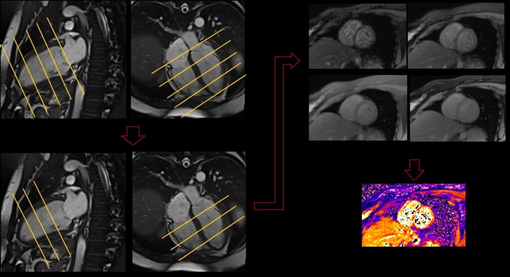
T1 mapping 3 out of 5 planning technique
Myocardial mapping is conducted within the short-axis plane, and the protocol consists of three slices. The initial slice is positioned at the apex, the second one at the mid-myocardium, and the final slice is targeted at the base of the ventricle. It is crucial to maintain an equal gap between these three slices. To enhance the precision of myocardial mapping planning, the 3 out of 5 planning technique has been introduced.
The 3 out of 5 planning method involves employing five slices initially, all with an identical slice gap, to comprehensively cover the entire ventricle in an end-diastolic phase. Users can subsequently reduce the number of slices to three, effectively eliminating one slice at the apex and one at the base. By adopting this technique, it ensures that the short-axis slices are meticulously positioned over the myocardium with the appropriate gap between them, facilitating accurate mapping.

T1 native mapping planning and protocols
Using the 3 out of 5 planning technique, plan the short-axis slices on the 2-chamber cine and angle the position block perpendicular to a line running through the center of the mitral valve and the left ventricular apex (i.e., perpendicular to the long axis of the left ventricle). Check the position in the other two planes. An appropriate angle must be established in the 4-chamber cine (perpendicular to the interventricular septum). While planning the five slices, adjust the slice gap to cover the entire ventricle. Then, reduce the slice number to three. These multi-slice short-axis mapping scans are performed with a combination of ECG gating and multiple breath-holds. Scans should be conducted during expiration breath-holds with one slice for each breath-hold. Short-axis mapping scans must be planned for the end-systole (maximum ventricular expansion) slice on the 2-chamber and 4-chamber cine.

Recommended Protocol
TR 280.6 | TE 1.12 | FLIP 35 | NEX 1 | SLICE 8MM | MATRIX 256X192 | FOV 360 | PHASE R>L | MAGN.PREP IR T1 MAP | TRIGGER YES |
Post contrast T1 mapping planning and protocols
Post contrast T1 mapping is performed after the administration of gadolinium. Planning should be copied from the Native T1 mapping.

Recommended Protocol
TR 280.6 | TE 1.12 | FLIP 35 | NEX 1 | SLICE 8MM | MATRIX 256X192 | FOV 360 | PHASE R>L | MAGN.PREP IR T1 MAP | TRIGGER YES |
T2 Mapping
T2 mapping leverages the T2 relaxation time, also known as transverse relaxation time, of various tissues to discern and characterize diverse pathological processes occurring within the myocardium. These pathological conditions can induce alterations in the T2 relaxation time of otherwise healthy tissues. For instance, certain pathologies can lead to myocardial edema, increasing the water content in normal myocardial tissues and consequently prolonging T2 relaxation times. Much like T1 mapping, it is essential to establish the baseline normal myocardial T2 values specific to each scanner. On our 1.5 T scanner, the approximate normal myocardial T2 values are 52 ± 3 ms, while on the 3T scanner, they measure 45 ± 1 ms. Two primary types of T2 mapping sequences are employed in myocardial imaging: the dark-blood turbo spin-echo (TSE) sequence and the bright-blood T2-preparation pulse-based sequences.
T2 mapping planning and protocols
Using the 3 out of 5 planning technique, plan the short-axis slices on the 2-chamber cine and angle the position block perpendicular to the line through the center of the mitral valve and the left ventricular apex (i.e., perpendicular to the long axis of the left ventricle). Verify the position in the other two planes. Provide an appropriate angle in the 4-chamber cine (perpendicular to the interventricular septum). While planning the 5 slices, adjust the slice gap to cover the entire ventricle. Then, reduce the number of slices to 3.
These multi-slice short-axis T2 mapping scans are performed using a combination of ECG gating and multiple breath-holds. Scans should be conducted during expiration breath-hold, with one slice acquired during each breath hold. Short-axis mapping scans must be planned for the end-systole (maximum ventricular expansion) slice in the 2-chamber and 4-chamber cine.

Recommended Protocol
TR 193.3 | TE 1.06 | FLIP 70 | NEX 1 | SLICE 8MM | MATRIX 192X192 | FOV 360 | PHASE R>L | MAGN.PREP T2 PREP | TRIGGER YES |
T2* Mapping
T2* mapping utilizes the T2* time of tissues to identify and characterize various pathological processes within the myocardium. It is primarily employed for detecting cardiac iron overload, which occurs in conditions such as sickle cell disease and hereditary hemochromatosis. Two distinct T2* mapping techniques are commonly used: the Bright-Blood Gradient Echo technique and the Black-Blood Gradient Echo technique.
In the Bright-Blood Gradient Echo technique, multiple gradient echo images are acquired with different echo times (TEs) ranging from 2 to 18 ms at 1.5T.
Conversely, the Black-Blood Gradient Echo scans employ a similar technique but incorporate additional double inversion pulses to suppress the blood pool. This approach results in homogeneous myocardial images with excellent contrast between the myocardium and its surroundings.
Interpreting the T2* values, a T2* greater than 20 ms indicates the absence of cardiac iron overload, while a range between 10 and 20 ms suggests mild to moderate iron loading. T2* values less than 10 indicate severe iron overload within the myocardium.
T2* mapping planning and protocols
Using the 3 out of 5 planning technique, plan the short-axis slices on the 2-chamber cine and angle the position block perpendicular to the line through the center of the mitral valve and the left ventricular apex (i.e., perpendicular to the long axis of the left ventricle). Verify the position in the other two planes. Provide an appropriate angle in the 4-chamber cine (perpendicular to the interventricular septum). While planning the 5 slices, adjust the slice gap to cover the entire ventricle. Then, reduce the number of slices to 3.
These multi-slice short-axis T2* mapping scans are performed using a combination of ECG gating and multiple breath-holds. Scans should be conducted during expiration breath-hold, with one slice acquired during each breath hold. Short-axis mapping scans must be planned for the end-systole (maximum ventricular expansion) slice in the 2-chamber and 4-chamber cine.
T2* Black-Blood planning

T2* Bright-Blood planning
Recommended Protocol
TR 700 | TE 2.08 4.10 6.12 8.14 10.16 12.18 14.20 16.22
| FLIP 20 | FAT SAT ON | SLICE 8MM | MATRIX 256X192 | FOV 360 | PHASE R>L | BH YES | TRIGGER YES |