Lumbar Spine MRI (Protocols and Planning)
Indications for lumbosacral spine MRI
- Localized back pain and radiculopathy with 6-week course of conservative care and inadequate response to treatment.
- Infectious or inflammatory processes (eg.spinal cord Abscess or spinal osteomyelitis)
- Myelopathies, Multiple Sclerosis and other demyelinating diseases
- Possible spinal cord injury and post-traumatic neurologic deficit
- Cauda equina syndrome, (e.g. sudden bowel/bladder disturbance).
- Evaluation or monitoring of congenital malformations of the spinal cord
- Evaluation or monitoring of inflammation of the CNS or meninges
- Evaluation or monitoring of tumour of the CNS or meninges
- Investigation of any cause of spinal disease in pregnancy
- Evaluation or monitoring of spinal cord compression
- Evaluation or monitoring of demyelinating disease
- Non-traumatic vascular injuries of the spine
- Reduced power on physical examination
- Monitoring of previous spinal surgery
- Evaluation or monitoring of trauma
- Spinal cord tumour
- Spine TB
Please check our new video tutorial for protocols and planning
Contraindications
- Any electrically, magnetically or mechanically activated implant (e.g. cardiac pacemaker, insulin pump biostimulator, neurostimulator, cochlear implant, and hearing aids)
- Intracranial aneurysm clips (unless made of titanium)
- Pregnancy (risk vs benefit ratio to be assessed)
- Ferromagnetic surgical clips or staples
- Metallic foreign body in the eye
- Metal shrapnel or bullet
Patient preparation for Lumbosacral spine MRI
- A satisfactory written consent form must be taken from the patient before entering the scanner room
- Ask the patient to remove all metal object including keys, coins, wallet, any cards with magnetic strips, jewellery, hearing aid and hairpins
- Ask the patient to undress and change into a hospital gown
- Contrast injection risk and benefits must be explained to the patient before the scan
- Gadolinium should only be given to the patient if GFR is > 30
- If possible, provide a chaperone for claustrophobic patients (e.g. relative or staff )
- Offer earplugs or headphones, possibly with music for extra comfort
- Explain the procedure to the patient
- Instruct the patient to keep still
- Note the weight of the patient
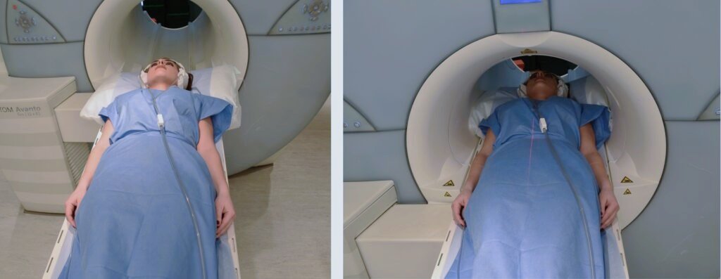
Positioning for Lumbosacral spine MRI
- Head first supine
- Position the paient in the spine coil and immobilise with cushions
- Give cushions under the legs for extra comfort
- Centre the laser beam localiser over the mid abdomen (4 inches above the iliac crest)
Recommended Lumbosacral Spine MRI Protocols and Planning
Lumbosacral spine MRI localiser
A three-plane localizer must be taken at the beginning to localize and plan the sequences. Localizers are usually less than 25 seconds and are T2\T1-weighted low-resolution scans.

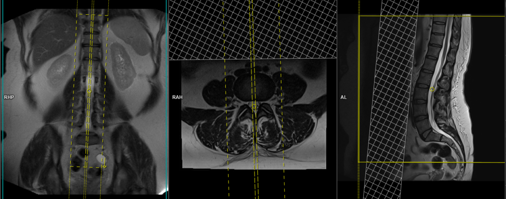
T2 tse sagittal 4mm
Plan the sagittal slices on the coronal plane and angle the position block parallel to the spinal cord. Check the positioning block in the other two planes, ensuring an appropriate angle is given in the axial plane (parallel to the center of the vertebral body and the spinous process). Verify the position block in the sagittal plane, ensuring the field of view (FOV) is big enough to cover the entire lumbar and sacral spine from T11 down to the coccyx (normally 350mm).
The slices should be sufficient to cover the spine from the lateral border of the right transverse process up to the lateral border of the left transverse process. To prevent peristalsis and breathing artifacts over the spinal area, place a saturation band over the abdomen (in front of the aorta) in the sagittal plane. Additionally, set the phase direction from head to feet to minimize further motion artifacts from the abdomen.
Parameters
TR 3000-4000 | TE 100-120 | SLICE 4MM | FLIP 130-150 | PHASE H>F | MATRIX 448X384 | FOV 350-350 | GAP 10% | NEX(AVRAGE) 2 |
T1 tse sagittal 4mm
Plan the sagittal slices on the coronal plane and angle the position block parallel to the spinal cord. Check the positioning block in the other two planes, ensuring an appropriate angle is given in the axial plane (parallel to the center of the vertebral body and the spinous process). Verify the position block in the sagittal plane, ensuring the field of view (FOV) is big enough to cover the entire lumbar and sacral spine from T11 down to the coccyx (normally 350mm).
The slices should be sufficient to cover the spine from the lateral border of the right transverse process up to the lateral border of the left transverse process. To prevent peristalsis and breathing artifacts over the spinal area, place a saturation band over the abdomen (in front of the aorta) in the sagittal plane. Additionally, set the phase direction from head to feet to minimize further motion artifacts from the abdomen.
Parameters
TR 400-600 | TE 15-25 | SLICE 4 MM | FLIP 150 | PHASE H>F | MATRIX 448X384 | FOV 350-350 | GAP 10% | NEX(AVRAGE) 2 |
T2 TSE STIR sagittal 4mm
Plan the sagittal slices on the coronal plane and angle the position block parallel to the spinal cord. Check the positioning block in the other two planes, ensuring an appropriate angle is given in the axial plane (parallel to the center of the vertebral body and the spinous process). Verify the position block in the sagittal plane, ensuring the field of view (FOV) is big enough to cover the entire lumbar and sacral spine from T11 down to the coccyx (normally 350mm).
The slices should be sufficient to cover the spine from the lateral border of the right transverse process up to the lateral border of the left transverse process. To prevent peristalsis and breathing artifacts over the spinal area, place a saturation band over the abdomen (in front of the aorta) in the sagittal plane. Additionally, set the phase direction from head to feet to minimize further motion artifacts from the abdomen.
Parameters
TR 4000-5000 | TE 110 | FLIP 150 | NEX 2 | SLICE 4MM | MATRIX 384X320 | FOV 350-350 | PHASE H>F | GAP 10% | TI 150 |
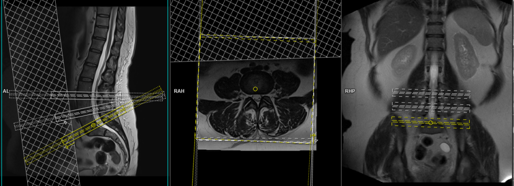
T2 TSE Axial multi block and multi angle
Plan the axial blocks on the sagittal plane: angle the first position block parallel to the L5-S1 intervertebral disc, the second position block parallel to the L4-L5 intervertebral disc, and the third position block parallel to the L3-L4 intervertebral disc (only three blocks are needed in a normal spine). Additional blocks must be taken in the presence of a prolapsed disc in any other levels.
An appropriate angle must be given in the coronal plane (parallel to the intervertebral disc space). Slices must be sufficient to cover the intervertebral discs (normally 5 slices for each disc space).
A saturation band must be placed over the abdomen (in front of the aorta) in the sagittal plane. This is to avoid peristalsis and breathing artifacts over the spinal area.
To prevent cross-talk artifacts, ensure that the blocks are not overlapping in the area of interest, particularly the spinal canal.
Parameters
TR 3000-4000 | TE 100-120 | SLICE 4 MM | FLIP 130-150 | PHASE A>P | MATRIX 320X320 | FOV 230-270 | GAP 10% | NEX(AVRAGE) 2 |
T1 TSE Axial multi block and multi angle
Plan the axial blocks on the sagittal plane: angle the first position block parallel to the L5-S1 intervertebral disc, the second position block parallel to the L4-L5 intervertebral disc, and the third position block parallel to the L3-L4 intervertebral disc (only three blocks are needed in a normal spine). Additional blocks must be taken in the presence of a prolapsed disc in any other levels.
An appropriate angle must be given in the coronal plane (parallel to the intervertebral disc space). Slices must be sufficient to cover the intervertebral discs (normally 5 slices for each disc space).
A saturation band must be placed over the abdomen (in front of the aorta) in the sagittal plane. This is to avoid peristalsis and breathing artifacts over the spinal area.
To prevent cross-talk artifacts, ensure that the blocks are not overlapping in the area of interest, particularly the spinal canal.
Parameters
TR 400-600 | TE 15-25 | SLICE 4 MM | FLIP 150 | PHASE A>P | MATRIX 320X320 | FOV 250-290 | GAP 10% | NEX(AVRAGE) 2 |
Indications for contrast enhancement spine scans
- Evaluation or monitoring of tumour of the CNS or meninges
- Monitoring of previous spinal surgery
- MS, hemipeligia/paresthesia and Infection
- Suspected spine lesions (e.g. bone Mets)
- Spinal cord tumour
- Syringomyelia
T2 TSE coronal 4mm large FOV for psoas abscess
Plan the coronal slices on the sagittal plane; angle the positioning block parallel to the psoas. Check the positioning block in the other two planes. An appropriate angle must be given in the axial plane (across the right and left psoas). Slices must be sufficient to cover the whole psoas from anterior to posterior. The FOV must be big enough to cover the whole psoas (normally 400mm-450mm) from T12 down to the lesser trochanter of the femur. Adding saturation bands in front of the coronal block will reduce artifacts from arterial pulsation and breathing.

Parameters
TR 4000-5000 | TE 110 | FLIP 150 | NEX 2 | SLICE 4 MM | MATRIX 384X384 | FOV 350-400 | PHASE H>F | GAP 10% | OVERSAMPLE 100% |
T2 TSE coronal 4mm large FOV lumbar spine
Plan the coronal slices on the sagittal plane; angle the positioning block parallel to the lumbar spine. Check the positioning block in the other two planes. An appropriate angle must be given in the axial plane (parallel to the right and left transverse processes). Slices must be sufficient to cover the entire lumbar spine from anterior to posterior. The field of view (FOV) must be large enough to encompass the whole lumbar spine (normally 400mm-450mm) from T10 to the S2. Adding saturation bands in front of the coronal block will reduce artifacts from arterial pulsation and breathing.

Parameters
TR 4000-5000 | TE 110 | FLIP 150 | NEX 2 | SLICE 4 MM | MATRIX 384X384 | FOV 350-400 | PHASE H>F | GAP 10% | OVERSAMPLE 100% |
T2 TSE single-block Axial for metastasis, fracture, or spinal TB
Plan the axial blocks on the sagittal plane: angle the first position block parallel to the lumbar spine. Additional blocks must be taken in the presence of pathology at any other levels. An appropriate angle should be given in the coronal plane (parallel to the intervertebral disc space). Ensure that the slices are sufficient to cover the pathology. Place a saturation band over the abdomen (in front of the aorta) in the sagittal plane. This is to avoid peristalsis and breathing artifacts over the spinal area.

Parameters
TR 4000-5000 | TE 100-120 | SLICE 4 MM | FLIP 130-150 | PHASE A>P | MATRIX 320X320 | FOV 230-270 | GAP 10% | NEX(AVRAGE) 2 |