Cervical Spine Exit Foramen View
Indications for mri cervical spine exit foramen view
- Arteriovenous malformation (AVM)
- Exit foramen neuroma
- Exit foramen tumors
- Disc sequestration
Note:-The MRI of the cervical spine exit foramen view is typically conducted as an extra or subsequent scan to the cervical spine MRI. This is done when there is a suspected issue located in the exit foramen, which is not well visualized in the standard cervical spine MRI images.
Contraindications
- Any electrically, magnetically or mechanically activated implant (e.g. cardiac pacemaker, insulin pump biostimulator, neurostimulator, cochlear implant, and hearing aids)
- Intracranial aneurysm clips (unless made of titanium)
- Pregnancy (risk vs benefit ratio to be assessed)
- Ferromagnetic surgical clips or staples
- Metallic foreign body in the eye
- Metal shrapnel or bullet
Patient preparation
- A satisfactory written consent form must be taken from the patient before entering the scanner room
- Ask the patient to remove all metal objects including keys, coins, wallet, cards with magnetic strips, jewellery, hearing aid and hairpins
- If possible provide a chaperone for claustrophobic patients (e.g. relative or staff )
- Contrast injection risk and benefits must be explained to the patient before the scan
- Gadolinium should only be given to the patient if GFR is > 30
- Offer earplugs or headphones, possibly with music for extra comfort
- Explain the procedure to the patient
- Instruct the patient to keep still
- Note the weight of the patient
Positioning
- Head first supine
- Position the head in the head and neck coil and immobilise with cushions
- Give cushions under the legs for extra comfort
- Centre the laser beam localiser over the mid neck (2.5cm below the chin in chin-down position)

Recommended Cervical Spine Exit foramen View Protocols and Planning
localiser
A three-plane localizer must be taken at the beginning to localize and plan the sequences. Localizers are normally less than 25 seconds, and they consist of T2\T1 weighted low-resolution scans.

T2 tse sagittal 3mm
Plan the sagittal slices on the coronal plane; angle the positioning block parallel to the spinal cord. Check the positioning block in the other two planes. An appropriate angle must be given in the axial plane (parallel to the line along the center of the vertebral body through the length of the spinous process). Check the positioning block in the sagittal plane; the field of view (FOV) must be big enough to cover the entire cervical spine from the pons down to T3 (normally 260mm). The slices must be sufficient to cover the spine from the lateral border of the right transverse process to the lateral border of the left transverse process. A saturation band must be placed over the neck (in front of the esophagus) in the sagittal plane. This is to avoid swallowing and pulsation artifacts over the spinal area. The phase direction should be head to foot to avoid motion artifacts from the neck.

Parameters
TR 3000-4000 | TE 100-120 | SLICE 3 MM | FLIP 130-150 | PHASE H>F | MATRIX 256X256 | FOV 280-290 | GAP 10% | NEX(AVRAGE) 2 |
T2 TSE Axial 3mm
Plan the axial slices on the sagittal plane and angle the position block perpendicular to the spinal cord. Additional blocks must be placed if there is a disc prolapse at any other level (e.g., T2, T3).. An appropriate angle must be given in the coronal plane, parallel to the intervertebral disc space. The slices should be sufficient to cover the entire C spine from C2 to T1. A saturation band must be placed over the neck (in front of the esophagus) in the sagittal plane. This is done to avoid swallowing and vascular pulsation artifacts over the spinal area.

Parameters
TR 4000-5000 | TE 90-120 | FLIP 150 | NEX 2 | SLICE 3 MM | MATRIX 256X256 | FOV 180-200 | PHASE A>P | GAP 10% | oversample 100% |
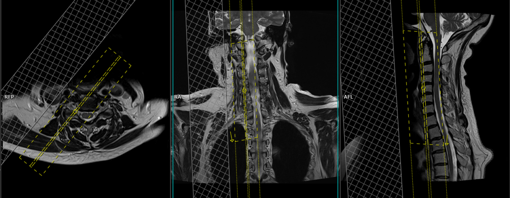
T2 TSE coronal oblique 2mm SFOV Right
Plan the right-side coronal oblique slices on the axial plane and align the planning block parallel to the exiting nerve roots. Verify the planning block in the other two planes. An appropriate angle should be applied in the sagittal plane, parallel to the spinal cord. The slices should sufficiently cover the exit foramen from the lower facet to the mid-vertebral body. Place a saturation band over the neck (in front of the block) in the axial plane. This is done to prevent swallowing and vascular pulsation artifacts over the exit foramen area. Use a slice thickness of 2mm or less to achieve the best results.

Parameters
TR 3000-4000 | TE 90-120 | FLIP 150 | NEX 3 | SLICE 2 MM | MATRIX 256X256 | FOV 180-200 | PHASE H>F | GAP 10% | oversample 100% |
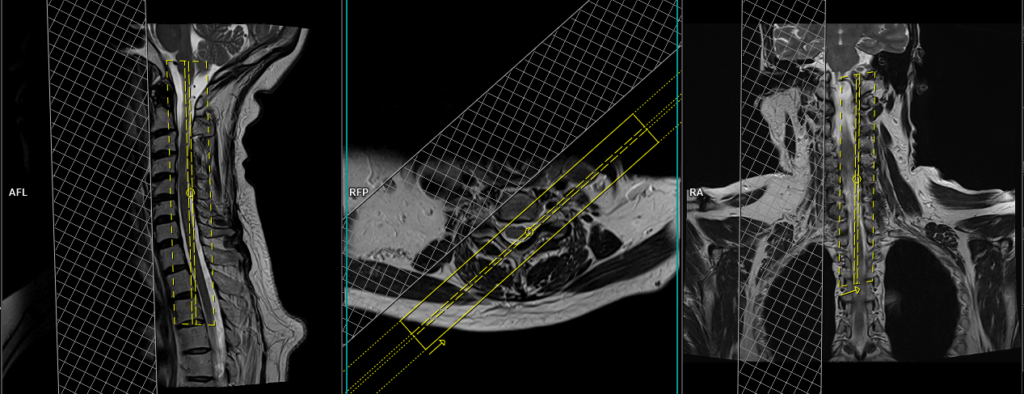
T2 TSE sagittal oblique 2mm SFOV Right
Plan the right-side sagittal oblique slices on the axial plane and align the planning block perpendicular to the exiting nerve roots. Verify the planning block in the other two planes. Apply an appropriate angle in the coronal plane, parallel to the spinal cord. The slices should adequately cover the exit foramen from the transverse process of the vertebra to the mid spinal cord. Position a saturation band over the neck (in front of the block) in the axial plane. This is done to prevent artifacts caused by swallowing and vascular pulsations in the exit foramen area. Utilize a slice thickness of 2mm or less to attain optimal results.

Parameters
TR 3000-4000 | TE 90-120 | FLIP 150 | NEX 3 | SLICE 2 MM | MATRIX 256X256 | FOV 180-200 | PHASE H>F | GAP 10% | oversample 100% |
T1 TSE sagittal oblique 2mm SFOV Right
Plan the right-side sagittal oblique slices on the axial plane and align the planning block perpendicular to the exiting nerve roots. Verify the planning block in the other two planes. Apply an appropriate angle in the coronal plane, parallel to the spinal cord. The slices should adequately cover the exit foramen from the transverse process of the vertebra to the mid spinal cord. Position a saturation band over the neck (in front of the block) in the axial plane. This is done to prevent artifacts caused by swallowing and vascular pulsations in the exit foramen area. Utilize a slice thickness of 2mm or less to attain optimal results.
Parameters
TR 400-500 | TE 15-20 | FLIP 150 | NEX 3 | SLICE 2 MM | MATRIX 256X256 | FOV 180-200 | PHASE H>F | GAP 10% | oversample 100% |
For contrast enhanced cervical spine exit foramen view
Use T1 TSE fat-saturated coronal oblique and sagittal onlique sequences after the administration of IV gadolinium DTPA injection (copy the planning outlined above). The document below provides access to the recommended dosage of gadolinium DTPA injection, as advised by the manufacturer.
Planning for left side
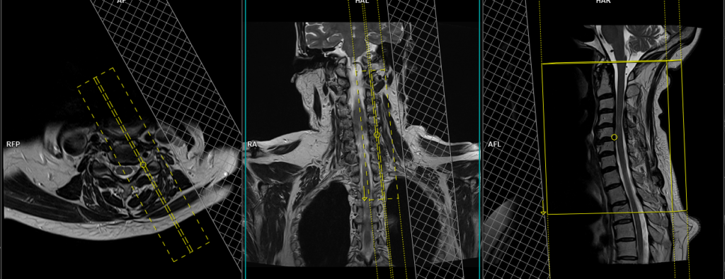
T2 TSE coronal oblique 2mm SFOV Left
Plan the left-side coronal oblique slices on the axial plane and align the planning block parallel to the exiting nerve roots. Verify the planning block in the other two planes. An appropriate angle should be applied in the sagittal plane, parallel to the spinal cord. The slices should sufficiently cover the exit foramen from the lower facet to the mid-vertebral body. Place a saturation band over the neck (in front of the block) in the axial plane. This is done to prevent swallowing and vascular pulsation artifacts over the exit foramen area. Use a slice thickness of 2mm or less to achieve the best results.
Parameters
TR 3000-4000 | TE 90-120 | FLIP 150 | NEX 2 | SLICE 2 MM | MATRIX 256X256 | FOV 180-200 | PHASE H>F | GAP 10% | oversample 100% |
T2 TSE sagittal oblique 2mm SFOV Left
Plan the left-side sagittal oblique slices on the axial plane and align the planning block perpendicular to the exiting nerve roots. Verify the planning block in the other two planes. Apply an appropriate angle in the coronal plane, parallel to the spinal cord. The slices should adequately cover the exit foramen from the transverse process of the vertebra to the mid spinal cord. Position a saturation band over the neck (in front of the block) in the axial plane. This is done to prevent artifacts caused by swallowing and vascular pulsations in the exit foramen area. Utilize a slice thickness of 2mm or less to attain optimal results.
Parameters
TR 3000-4000 | TE 90-120 | FLIP 150 | NEX 3 | SLICE 2 MM | MATRIX 256X256 | FOV 180-200 | PHASE H>F | GAP 10% | oversample 100% |