MRI Cervical Spine
Indications for MRI cervical spine
- Persistent neck pain or radiculopathy with 6-week course of conservative care and inadequate > response to treatment.
- Cancer or tumours of the spine (cancer of the spine, spinal cord, or meninges)
- Evaluation or monitoring of congenital malformations of the spinal cord
- Myelopathies, Multiple Sclerosis and other demyelinating disease
- Possible spinal cord injury and post-traumatic neurologic deficit
- Post-operative evaluation, with new neurologic findings
- Congenital or acquired spinal abnormalities in children
- Fracture evaluation for suspected or known fracture.
- Infectious or inflammatory processes
- Evaluation or monitoring of myelopathy
- Monitoring of previous spinal surgery
- Evaluation or monitoring of syrinx
- Spinal injury or trauma
- Spinal cord tumour
- Spinal TB
Contraindications
- Any electrically, magnetically or mechanically activated implant (e.g. cardiac pacemaker, insulin pump biostimulator, neurostimulator, cochlear implant, and hearing aids)
- Intracranial aneurysm clips (unless made of titanium)
- Pregnancy (risk vs benefit ratio to be assessed)
- Ferromagnetic surgical clips or staples
- Metallic foreign body in the eye
- Metal shrapnel or bullet
Patient preparation for MRI Cervical Spine
- A satisfactory written consent form must be taken from the patient before entering the scanner room
- Ask the patient to remove all metal objects including keys, coins, wallet, cards with magnetic strips, jewellery, hearing aid and hairpins
- If possible provide a chaperone for claustrophobic patients (e.g. relative or staff )
- Contrast injection risk and benefits must be explained to the patient before the scan
- Gadolinium should only be given to the patient if GFR is > 30
- Offer earplugs or headphones, possibly with music for extra comfort
- Explain the procedure to the patient
- Instruct the patient to keep still
- Note the weight of the patient
Positioning for MRI Cervical Spine
- Head first supine
- Position the head in the head and neck coil and immobilise with cushions
- Give cushions under the legs for extra comfort
- Centre the laser beam localiser over the mid neck (2.5cm below the chin in chin-down position)

Recommended MRI Cervical Spine Protocols and Planning
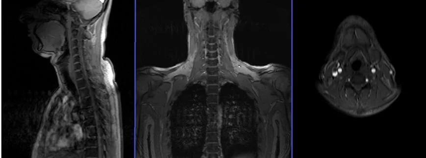
MRI Cervical Spine localiser
A three-plane localizer must be taken at the beginning to localize and plan the sequences. Localizers are normally less than 25 seconds, and they consist of T1-weighted low-resolution scans.
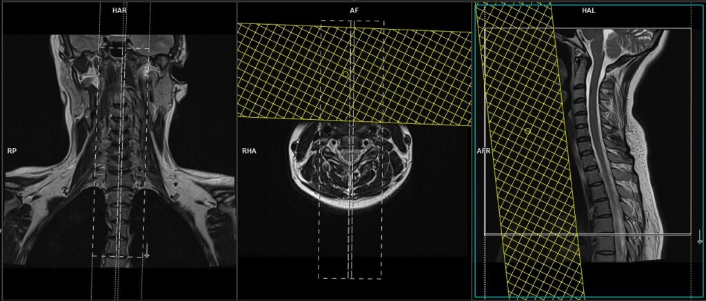
T2 tse sagittal 3mm
Plan the sagittal slices on the coronal plane; angle the positioning block parallel to the spinal cord. Check the positioning block in the other two planes. An appropriate angle must be given in the axial plane (parallel to the line along the center of the vertebral body through the length of the spinous process). Check the positioning block in the sagittal plane; the field of view (FOV) must be big enough to cover the entire cervical spine from the pons down to T3 (normally 260mm). The slices must be sufficient to cover the spine from the lateral border of the right transverse process to the lateral border of the left transverse process. A saturation band must be placed over the neck (in front of the esophagus) in the sagittal plane. This is to avoid swallowing and pulsation artifacts over the spinal area. The phase direction should be head to foot to avoid motion artifacts from the neck.
Parameters
TR 3000-4000 | TE 100-120 | SLICE 3 MM | FLIP 130-150 | PHASE H>F | MATRIX 256X256 | FOV 280-290 | GAP 10% | NEX(AVRAGE) 2 |
T1 tse sagittal 3mm
Plan the sagittal slices on the coronal plane; angle the positioning block parallel to the spinal cord. Check the positioning block in the other two planes. An appropriate angle must be given in the axial plane (parallel to the line along the center of the vertebral body through the length of the spinous process). Check the positioning block in the sagittal plane; the field of view (FOV) must be big enough to cover the entire cervical spine from the pons down to T3 (normally 260mm). The slices must be sufficient to cover the spine from the lateral border of the right transverse process to the lateral border of the left transverse process. A saturation band must be placed over the neck (in front of the esophagus) in the sagittal plane. This is to avoid swallowing and pulsation artifacts over the spinal area. The phase direction should be head to foot to avoid motion artifacts from the neck.
Parameters
TR 400-600 | TE 15-25 | SLICE 3 MM | FLIP 150 | PHASE H>F | MATRIX 256X256 | FOV 280-290 | GAP 10% | NEX(AVRAGE) 2 |
T2 STIR sagittal 3mm
Plan the sagittal slices on the coronal plane; angle the positioning block parallel to the spinal cord. Check the positioning block in the other two planes. An appropriate angle must be given in the axial plane (parallel to the line along the center of the vertebral body through the length of the spinous process). Check the positioning block in the sagittal plane; the field of view (FOV) must be big enough to cover the entire cervical spine from the pons down to T3 (normally 260mm). The slices must be sufficient to cover the spine from the lateral border of the right transverse process to the lateral border of the left transverse process. A saturation band must be placed over the neck (in front of the esophagus) in the sagittal plane. This is to avoid swallowing and pulsation artifacts over the spinal area. The phase direction should be head to foot to avoid motion artifacts from the neck.
Parameters
TR 7000-9000 | TE 110 | FLIP 150 | NEX 2 | SLICE 3 MM | MATRIX 256X256 | FOV 280 | PHASE H>F | GAP 10% | TI 150 |
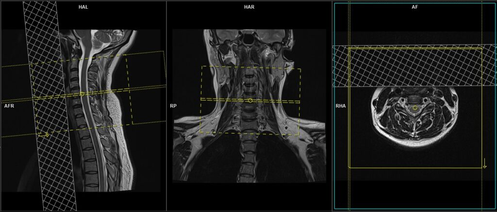
T2 TSE Axial 3mm
Plan the axial slices on the sagittal plane and angle the position block perpendicular to the spinal cord. Additional blocks must be placed if there is a disc prolapse at any other level (e.g., T2, T3).. An appropriate angle must be given in the coronal plane, parallel to the intervertebral disc space. The slices should be sufficient to cover the entire C spine from C2 to T1. A saturation band must be placed over the neck (in front of the esophagus) in the sagittal plane. This is done to avoid swallowing and vascular pulsation artifacts over the spinal area.
Parameters
TR 3000-4000 | TE 90-120 | FLIP 150 | NEX 2 | SLICE 3 MM | MATRIX 256X256 | FOV 180-200 | PHASE A>P R>L | GAP 10% | oversample 100% |
T1 TSE Axial 3mm
Plan the axial slices on the sagittal plane and angle the position block perpendicular to the spinal cord. Additional blocks must be placed if there is a disc prolapse at any other level (e.g., T2, T3).. An appropriate angle must be given in the coronal plane, parallel to the intervertebral disc space. The slices should be sufficient to cover the entire C spine from C2 to T1. A saturation band must be placed over the neck (in front of the esophagus) in the sagittal plane. This is done to avoid swallowing and vascular pulsation artifacts over the spinal area.
Parameters
TR 400-500 | TE 15-20 | FLIP 150 | NEX 2 | SLICE 3 MM | MATRIX 256X256 | FOV 180-200 | PHASE A>P R>L | GAP 10% | oversample 100% |
Indications For contrast enhanced cervical spine scan
- Evaluation or monitoring of tumour of the CNS or meninges
- Monitoring of previous spinal surgery
- Suspected spine lesions (e.g. bone mets)
- Spinal cord tumour
- Syringomyelia
Additional sequences for spinal AVM and lesions obscured by CSF flow.
T2 SPACE 3D sagittal 0.7 mm isotropic
Plan the sagittal 3D block on the coronal localizer, angling the positioning block parallel to the spinal cord. Verify the positioning block in the other two planes. In the axial plane, ensure the block is angled appropriately, parallel to the line running through the center of the vertebral body along the length of the spinous process. Check the positioning block in the sagittal plane to ensure the field of view (FOV) is large enough to cover the entire cervical spine, from the pons down to T2 (typically 250mm). The slices should sufficiently cover the spine from the lateral border of the right transverse process to the lateral border of the left transverse process. Place a saturation band over the neck (in front of the esophagus) in the sagittal plane to avoid swallowing and pulsation artifacts over the spinal area. The phase direction should be head to foot to prevent motion artifacts from the neck.

Parameters
TR 1500-2000 | TE 250-350 | SLICE 0.7 MM | FLIP 120-150 | PHASE H>F | MATRIX 320X320 | FOV 250-260 | GAP 20% | NEX(AVRAGE) 1.4 |