Cerebrospinal fluid (CSF) flow MRI: Protocol and planning
CSF Flow quantification MRI
A cerebrospinal fluid (CSF) flow MRI is a specialized type of MRI scan used to visualize the flow of cerebrospinal fluid within the brain and spinal canal. In a CSF flow MRI, the goal is to assess the dynamics of this fluid to ensure it is moving properly throughout the brain and spinal column. Disturbances in CSF flow can be indicative of various medical conditions, such as hydrocephalus , spinal stenosis, or Chiari malformations (where brain tissue extends into the spinal canal).
This imaging technique utilizes specific MRI sequences that are sensitive to the movement of fluids. By using phase-contrast techniques, the MRI can capture and create visual and quantitative data on the direction and speed of CSF flow. This data is crucial for diagnosing abnormalities in fluid pathways and guiding treatment decisions.
The CSF flow MRI uses specific sequences that are sensitive to the movement of fluids within the body. The most common types of sequences used in CSF flow MRI include:
- Phase-Contrast (PC) MRI Sequences: These are the most widely used sequences for CSF flow studies. They work by measuring phase shifts in the MR signal caused by the movement of CSF. This allows the visualization of the direction and velocity of CSF flow. Phase-contrast sequences can be set to be sensitive to specific directions and speeds of flow, making them highly effective for assessing CSF dynamics.
- Cine MRI: This technique captures multiple frames within a cycle of CSF movement, effectively creating a video of CSF flow. Cine MRI is beneficial in showing how CSF flow changes over time.
- 3D Volumetric Sequences: These sequences provide detailed three-dimensional images of the CSF spaces and can be helpful in assessing the overall anatomy and any potential abnormalities affecting CSF flow
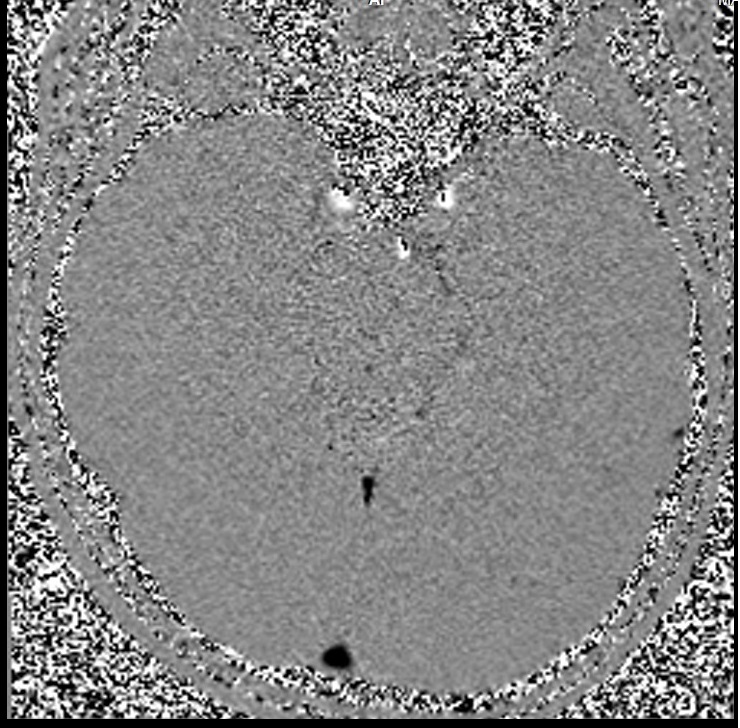
Through-plane CSF flow MRI images
Re-phased Image
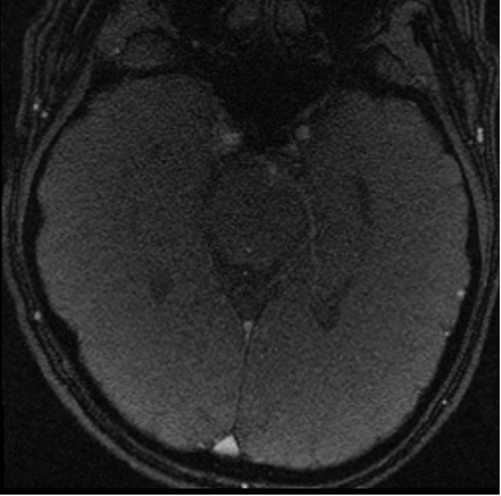
Magnitude Image
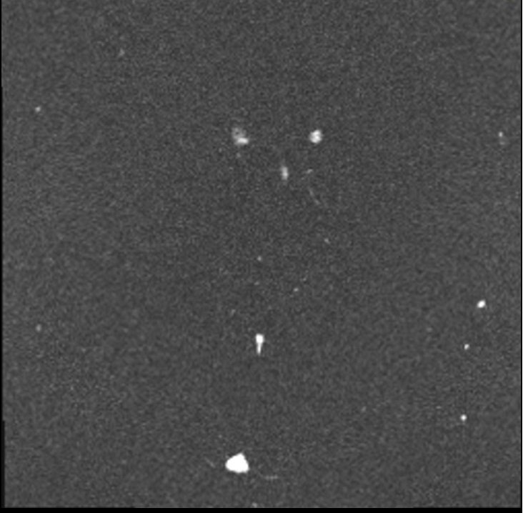
Phase Image
indications for Cerebrospinal fluid (CSF) flow MRI
- Hydrocephalus Diagnosis and Management
- Congenital Malformation
- Chiari Malformation
- Assessment of CSF Leak
- Spinal Cord Pathologies
- Evaluation of Post-Surgical Changes
- Tumor Evaluation
Contraindications
- Any electrically, magnetically or mechanically activated implant (e.g. cardiac pacemaker, insulin pump biostimulator, neurostimulator, cochlear implant, and hearing aids)
- Intracranial aneurysm clips (unless made of titanium)
- Pregnancy (risk vs benefit ratio to be assessed)
- Ferromagnetic surgical clips or staples
- Metallic foreign body in the eye
- Metal shrapnel or bullet
Patient preparation for CSF flow MRI
- A satisfactory written consent form must be taken from the patient before entering the scanner room
- Ask the patient to remove all metal objects including keys, coins, wallet, cards with magnetic strips, jewellery, hearing aid and hairpins
- Ask the patient to undress and change into a hospital gown
- Request the patient to use the rest room before procedure
- Follow the appropriate manufacturer's instructions for the pulse oximeter and its Bluetooth receiver placement.
- Claustrophobic patients may be accompanied into the scanner room e.g. by staff member or relative with proper safety screening
- Offer headphones and earplugs for communicating with the patient and for ear protection.
- Explain the procedure to the patient and answer questions
- Note the hight and weight of the patient
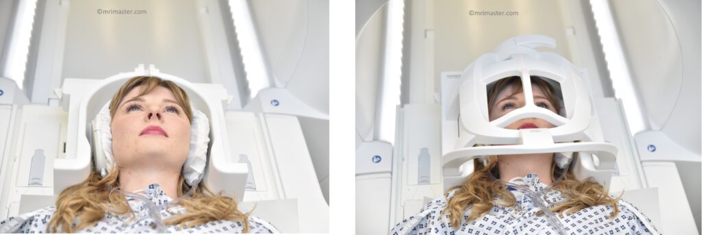
Positioning for CSF Flow MRI
- Head first supine
- Position the head in the head coil and immobilise with cushions
- Connect the MRI vendor's pulse oximeter module in accordance with the specific manufacturer’s instructions.
- Check the quality of the pulse signal on the integrated pulse display of the scanner terminal. If the signal is unsatisfactory or inconsistent, switch the finger to which the probe is connected.
- Give cushions under the legs for extra comfort
- Now, connect the top portion of the head coil and secure it in place.
- Centre the laser beam localiser over the glabella
Pulse gating technique
Cerebrospinal fluid (CSF) flow imaging is performed using pulse gating techniques to synchronize the imaging with the cardiac cycle. This synchronization is crucial because the flow of CSF is influenced by the cardiac pulse, which causes periodic fluctuations in the pressure gradients across the central nervous system. As the heart beats, it not only pumps blood but also subtly affects the movement of CSF, making its dynamics inherently pulsatile.
Pulse gating in CSF flow imaging typically involves the use of electrocardiogram (ECG) or peripheral pulse gating to capture the precise phases of the cardiac cycle. By coordinating the MRI scans with these phases, it becomes possible to obtain highly detailed and dynamic images of CSF flow. This method allows for the measurement of CSF velocity and flow patterns at different times within the cardiac cycle, providing a comprehensive view of its temporal and spatial variations.

Recommended CSF Flow MRI Protocols and Planning
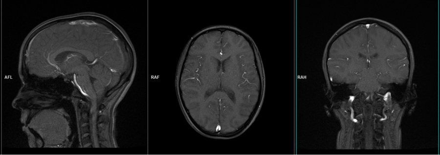
Localiser
A three-plane localizer must be taken at the beginning to localize and plan the sequences. Localizers are usually less than 25 seconds and are T1-weighted low-resolution scans.
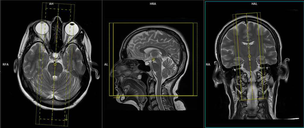
T2 tse axial
Plan the axial slices on the sagittal plane and position the block parallel to the genu and splenium of the corpus callosum. Verify the planning block in the other two planes and ensure that an appropriate angle is maintained in the coronal plane, making it perpendicular to the line of the midline of the brain and the 4th ventricle. Ensure that the number of slices is sufficient to cover the entire brain from the vertex to the line of the foramen magnum.

Protocol Parameters of T2
TR 4000-5500 | TE 100-120 | SLICE 3MM | FLIP 130-150 | PHASE R>L | MATRIX 320X320 | FOV 210-230 | GAP 10% | NEX(AVRAGE) 2 |
T2 FLAIR coronal
Plan the coronal slices on the sagittal plane and angle the planning block perpendicular to the line along the genu and splenium of the corpus callosum. Verify the planning block in the other two planes. Ensure that an appropriate angle is maintained in the axial plane, perpendicular to the midline of the brain. The number of slices should be sufficient to cover the entire brain from the frontal sinus to the line of the occipital protuberance.

Protocol Parameters of FLAIR
TR 7000-9000 | TE 110 | FLIP 130 | NEX 2 | SLICE 3MM | MATRIX 320X320 | FOV 210-230 | PHASE R>L | GAP 10% | TI 2500 |
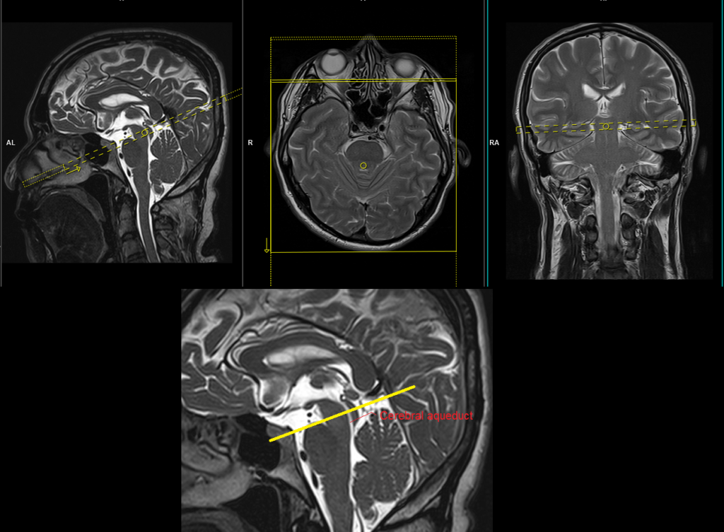
T2 SPACE 3D Mid-brain Sagittal 0.5 mm
Plan the sagittal slices on the axial plane and position the block parallel to the midline of the brain. Verify the planning block in the other two planes. Angle the planning block appropriately in the coronal plane, ensuring it is parallel to the line along the midline of the brain and the fourth ventricle. Make sure that the number of slices is sufficient to cover the entire brainstem from one side to the other.
Protocol Parameters of SPACE 3D
TR 2500-3500 | TE 100-130 | SLICE .5mm | FLIP 80 | PHASE R>L | MATRIX 330X320 | FOV 210-230 | GAP 20% | NEX(AVRAGE) 1 |
3D SPACE sagittal Images


CSF flow and VENC settings
Normal CSF flow velocities can vary significantly based on the individual, the location measured, and physiological conditions, but general guidelines include:
- Peak systolic velocities range from 5 to 10 cm/s in the cerebral aqueduct.
- VENC settings are often set around 5 to 25 cm/s, depending on the expected velocity of CSF flow in the region of interest.
The ideal method for conducting a CSF flow sequence involves using a VENC scout to identify the optimal flow value. However, radiographers often find it challenging to determine this optimal value. For this reason, we prefer to perform multiple scans with different VENC settings. Since the scan time is very short per sequence, performing multiple VENC scans takes almost the same amount of time as performing the scans with a VENC scout.
CSF flow through- plane scan protocol and planning
CSF flow through plane VENC 6cm\sec
Plan the axial flow sequence using the sagittal 3D SPACE image that shows the cerebral aqueduct, and position the block perpendicular to the cerebral aqueduct. Verify the placement of the planning block in the other two planes, ensuring that it maintains an appropriate angle in the coronal plane, making it perpendicular to the brain’s midline.
Protocol Parameters
TR 42.3 | TE 3.1 | FLIP 20 | NEX 1 | SLICE 6MM | MATRIX 208×192 | FOV 200 | PHASE R>L | VELOCITY 6cm\sec | TRIGGER Pulse |
CSF flow study image Images
Re-phased Image
Magnitude Image
Phase Image
CSF flow through plane VENC 10cm\sec
Plan the axial flow sequence using the sagittal 3D SPACE image that shows the cerebral aqueduct, and position the block perpendicular to the cerebral aqueduct. Verify the placement of the planning block in the other two planes, ensuring that it maintains an appropriate angle in the coronal plane, making it perpendicular to the brain’s midline.
Protocol Parameters
TR 21.1 | TE 6.38 | FLIP 20 | NEX 1 | SLICE 6MM | MATRIX 224×205 | FOV 160 | PHASE A>P | VELOCITY 10cm\sec | TRIGGER Pulse/Retro |
CSF flow through plane VENC 15cm\sec
Plan the axial flow sequence using the sagittal 3D SPACE image that shows the cerebral aqueduct, and position the block perpendicular to the cerebral aqueduct. Verify the placement of the planning block in the other two planes, ensuring that it maintains an appropriate angle in the coronal plane, making it perpendicular to the brain’s midline.
Protocol Parameters
TR 21.1 | TE 6.38 | FLIP 20 | NEX 1 | SLICE 6MM | MATRIX 224×205 | FOV 160 | PHASE A>P | VELOCITY 15cm\sec | TRIGGER Pulse/Retro |
CSF flow through plane VENC 20cm\sec
Plan the axial flow sequence using the sagittal 3D SPACE image that shows the cerebral aqueduct, and position the block perpendicular to the cerebral aqueduct. Verify the placement of the planning block in the other two planes, ensuring that it maintains an appropriate angle in the coronal plane, making it perpendicular to the brain’s midline.
Protocol Parameters
TR 21.1 | TE 6.38 | FLIP 20 | NEX 1 | SLICE 6MM | MATRIX 224×205 | FOV 160 | PHASE A>P | VELOCITY 20cm\sec | TRIGGER Pulse/Retro |
CSF flow through plane VENC 25cm\sec
Plan the axial flow sequence using the sagittal 3D SPACE image that shows the cerebral aqueduct, and position the block perpendicular to the cerebral aqueduct. Verify the placement of the planning block in the other two planes, ensuring that it maintains an appropriate angle in the coronal plane, making it perpendicular to the brain’s midline.
Protocol Parameters
TR 21.1 | TE 6.38 | FLIP 20 | NEX 1 | SLICE 6MM | MATRIX 224×205 | FOV 160 | PHASE A>P | VELOCITY 25cm\sec | TRIGGER Pulse/Retro |
CSF flow through plane VENC 30cm\sec
Plan the axial flow sequence using the sagittal 3D SPACE image that shows the cerebral aqueduct, and position the block perpendicular to the cerebral aqueduct. Verify the placement of the planning block in the other two planes, ensuring that it maintains an appropriate angle in the coronal plane, making it perpendicular to the brain’s midline.
Protocol Parameters
TR 21.1 | TE 6.38 | FLIP 20 | NEX 1 | SLICE 6MM | MATRIX 224×205 | FOV 160 | PHASE A>P | VELOCITY 30cm\sec | TRIGGER Pulse/Retro |
CSF flow through plane VENC 45cm\sec
Plan the axial flow sequence using the sagittal 3D SPACE image that shows the cerebral aqueduct, and position the block perpendicular to the cerebral aqueduct. Verify the placement of the planning block in the other two planes, ensuring that it maintains an appropriate angle in the coronal plane, making it perpendicular to the brain’s midline.
Protocol Parameters
TR 21.1 | TE 6.38 | FLIP 20 | NEX 1 | SLICE 6MM | MATRIX 224×205 | FOV 160 | PHASE A>P | VELOCITY 45cm\sec | TRIGGER Pulse/Retro |
The post-processing of the study is performed by the radiologist at the workstation. Each manufacturer has its own post-processing software. However, if anyone is interested in learning more about this, please refer to the manufacturer’s scanner manual.
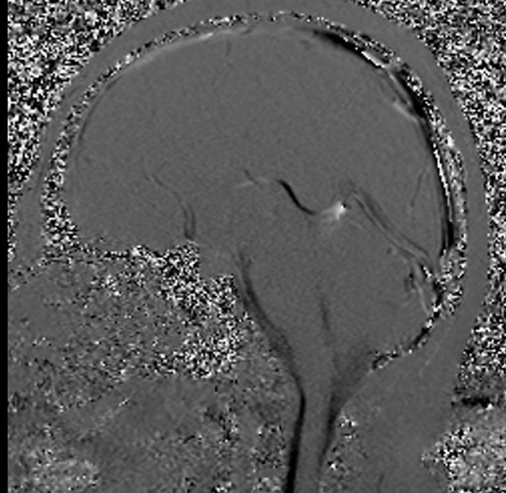
CSF flow in- plane scan protocol and planning
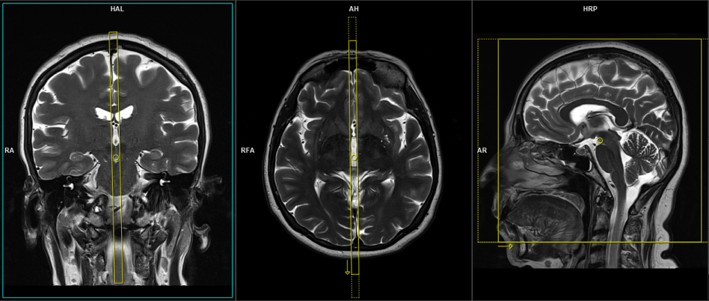
CSF flow in-plane VENC 6cm\sec
Plan the sagittal flow sequence on the axial plane and position the block parallel to the midline of the brain. Verify the planning block in the other two planes. Angle the planning block appropriately in the coronal plane to ensure it is parallel to the line along the midline of the brain and the third ventricle. Make sure that pulse gating is enabled in the protocol.
Protocol Parameters
TR 23.7 | TE 7.78 | FLIP 20 | NEX 1 | SLICE 6MM | MATRIX 256×205 | FOV 180 | PHASE A>P | VELOCITY 6cm\sec | TRIGGER Pulse/Retro |
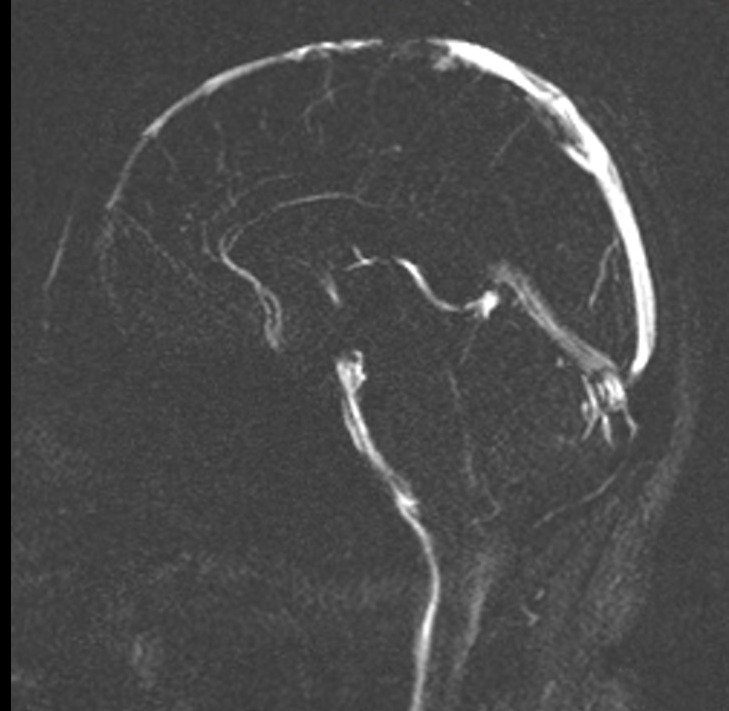
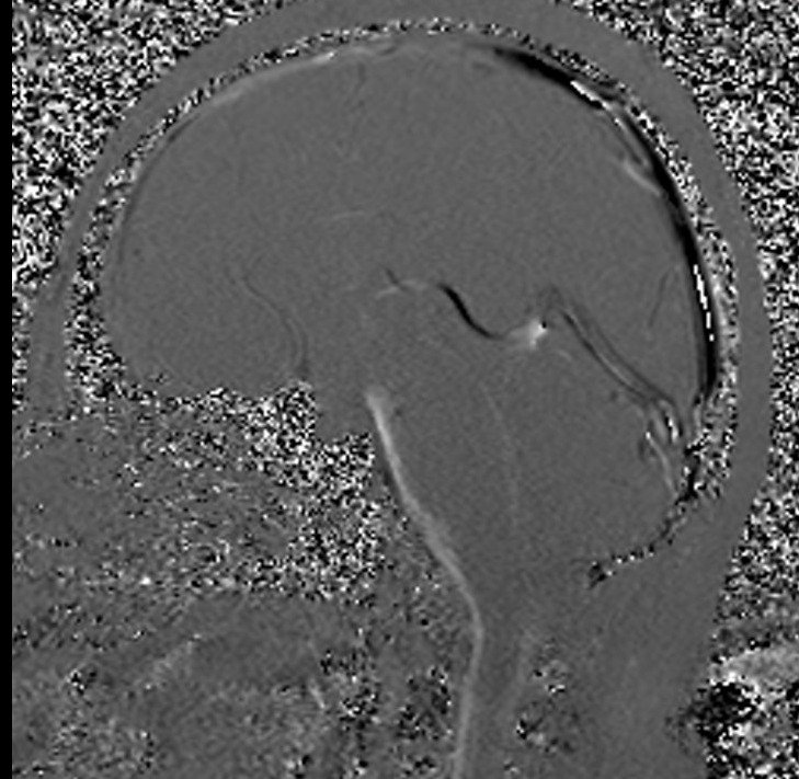
CSF flow study image Images
Re-phased Image

Magnitude Image

Phase Image
Re-phased Image
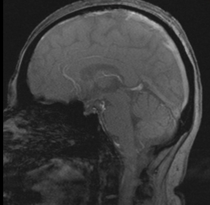
Magnitude Image
Phase Image
Re-phased Image

Magnitude Image

Phase Image
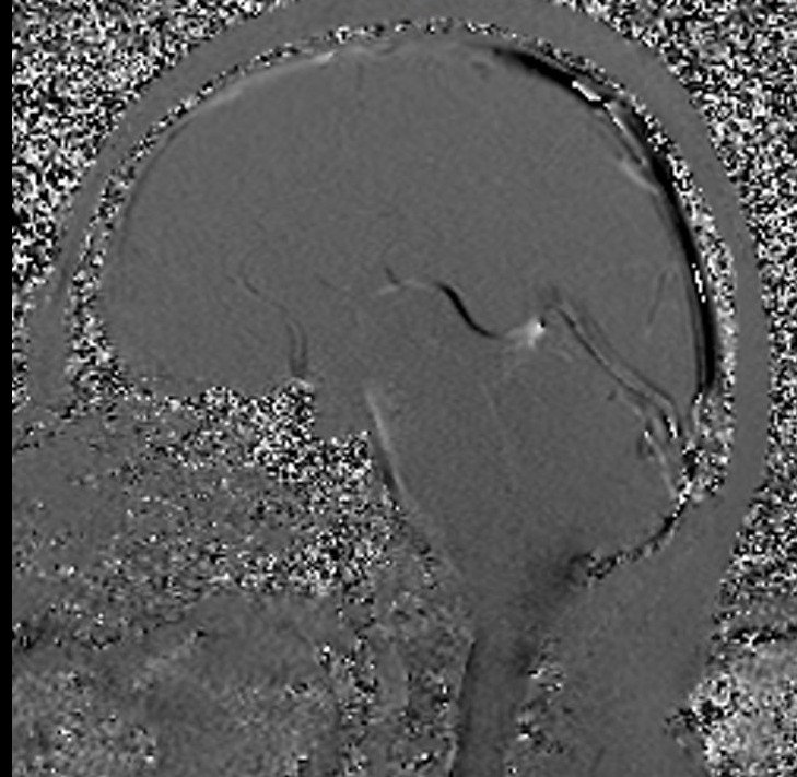
CSF flow in-plane VENC 6cm\sec
Plan the sagittal flow sequence on the axial plane and position the block parallel to the midline of the brain. Verify the planning block in the other two planes. Angle the planning block appropriately in the coronal plane to ensure it is parallel to the line along the midline of the brain and the third ventricle. Make sure that pulse gating is enabled in the protocol.
Protocol Parameters
TR 23.7 | TE 7.78 | FLIP 20 | NEX 1 | SLICE 6MM | MATRIX 256×205 | FOV 180 | PHASE A>P | VELOCITY 6cm\sec | TRIGGER Pulse/Retro |
CSF flow study image Images
Re-phased Image
Magnitude Image
Phase Image
Re-phased Image
Magnitude Image
Phase Image
Re-phased Image
Magnitude Image
Phase Image
CSF flow in-plane VENC 11cm\sec
Plan the sagittal flow sequence on the axial plane and position the block parallel to the midline of the brain. Verify the planning block in the other two planes. Angle the planning block appropriately in the coronal plane to ensure it is parallel to the line along the midline of the brain and the third ventricle. Make sure that pulse gating is enabled in the protocol.
Protocol Parameters
TR 23.7 | TE 7.78 | FLIP 20 | NEX 1 | SLICE 6MM | MATRIX 256×205 | FOV 180 | PHASE A>P | VELOCITY 11cm\sec | TRIGGER Pulse/Retro |
CSF flow in-plane VENC 20cm\sec
Plan the sagittal flow sequence on the axial plane and position the block parallel to the midline of the brain. Verify the planning block in the other two planes. Angle the planning block appropriately in the coronal plane to ensure it is parallel to the line along the midline of the brain and the third ventricle. Make sure that pulse gating is enabled in the protocol.
Protocol Parameters
TR 23.7 | TE 7.78 | FLIP 20 | NEX 1 | SLICE 6MM | MATRIX 256×205 | FOV 180 | PHASE A>P | VELOCITY 20cm\sec | TRIGGER Pulse/Retro |
CSF flow in-plane VENC 25cm\sec
Plan the sagittal flow sequence on the axial plane and position the block parallel to the midline of the brain. Verify the planning block in the other two planes. Angle the planning block appropriately in the coronal plane to ensure it is parallel to the line along the midline of the brain and the third ventricle. Make sure that pulse gating is enabled in the protocol.
Protocol Parameters
TR 23.7 | TE 7.78 | FLIP 20 | NEX 1 | SLICE 6MM | MATRIX 256×205 | FOV 180 | PHASE A>P | VELOCITY 25cm\sec | TRIGGER Pulse/Retro |