MRI Bandwidth and Image Quality
Introduction
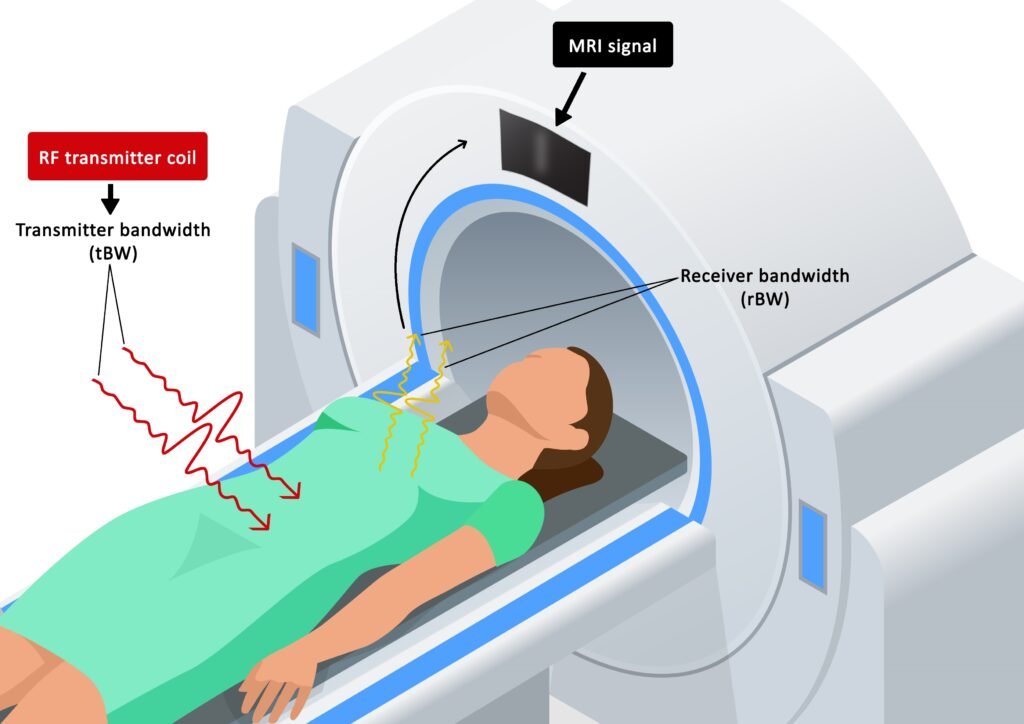
In MRI, bandwidth is defined as the range of frequencies or wavelengths that can be transmitted or received within a limited amount of time. Bandwidth is measured in cycles per second, or Hertz (Hz). An MRI sequence is designed with two types of bandwidths: transmitter bandwidth (tBW) and receiver bandwidth (rBW). Transmitter bandwidth describes the properties of the transmitted radiofrequency (RF) pulses, while receiver bandwidth describes the quality of the MRI signal.
Transmitter Bandwidth (tBW)
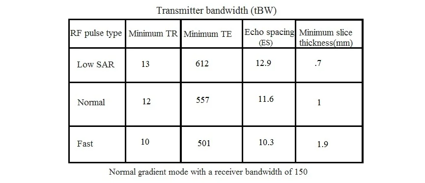
Transmitter bandwidth refers to the bandwidth utilized during the transmission of RF pulses. It is employed to excite a discrete slice thickness or volume. The minimum achievable slice thickness of a pulse sequence is directly proportional to the transmitter bandwidth of the RF pulse type; in other words, the higher the transmitter bandwidth, the smaller the achievable slice thickness.
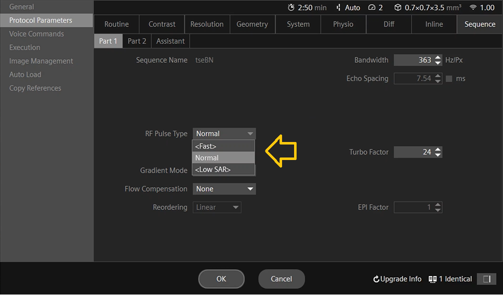
Siemens scanners offer three types of RF pulses in most of their sequences: a low specific absorption rate (SAR) option, which employs a low bandwidth pulse; a normal option, which utilizes a medium bandwidth pulse; and a Fast option, which employs a higher bandwidth pulse.
Low SAR
This is a low-bandwidth RF pulse with a very good slice profile, which allows for less crosstalk between slices. This option enables you to choose the lowest possible slice thickness in most pulse sequences. This RF pulse type results in reduced SAR values. Choosing this option reduces the likelihood of the sequence going into the first-level mode. One disadvantage of the low SAR RF pulse type is longer scan times due to longer minimum TEs, TRs, and echo spacing (the time from one echo to the next echo). Additionally, the low transmitter bandwidth pulse type is more susceptible to susceptibility and distortion artifacts.
Normal
This is a medium bandwidth RF pulse with a good slice profile and optimized SAR behavior.
Fast
This is a high-bandwidth RF pulse with a compromised slice profile, which will result in a higher SAR compared to the other modes. This type of RF pulse provides users with an opportunity to reduce TEs and TRs. It has a shorter echo spacing (ES) and very minimal susceptibility and distortion artifacts. It should be noted that a Fast RF pulse carries a higher risk of peripheral nerve stimulation.
Practical applications of low transmitter bandwidth (Low SAR mode)
Low transmitter bandwidth mode is the most appropriate option to choose when scanning neonates and sedated patients because they are unable to provide feedback to the operator. The low SAR mode must be selected when scanning pregnant patients to avoid any potential RF harm to the fetus. Low transmitter bandwidth RF pulses are also useful for scanning patients with MRI conditional implants, such as MRI conditional pacemakers and heart valves.
Practical applications of high transmitter bandwidth (Fast mode)
High transmitter bandwidth can be effectively utilized to decrease scan times in claustrophobic and moving patients. This approach will significantly lower the minimum TR and TE values, enabling the user to manually reduce TR and TE values, thereby reducing scan time. The primary drawback of this method is that shortening the TEs and TRs typically leads to increased noise and a higher potential for peripheral stimulation. The diagrams below illustrate how to select these options and present the results of the manipulations.
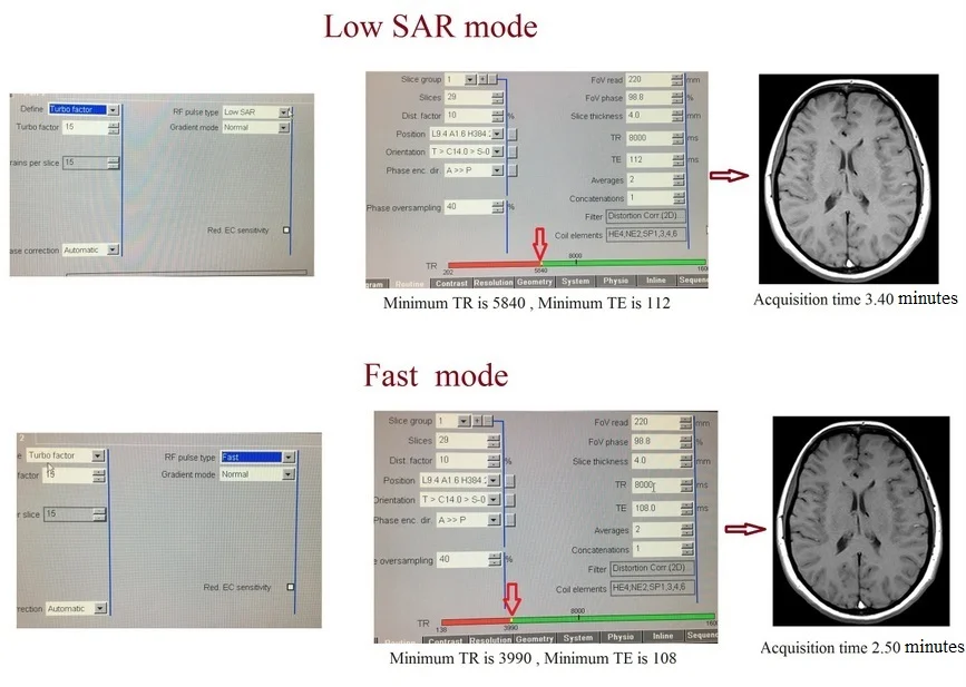
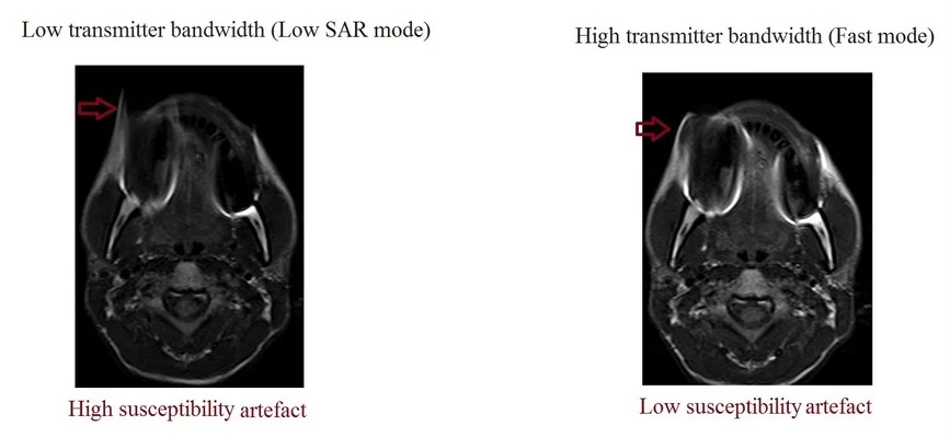
High transmitter bandwidth is the most appropriate option to select when scanning areas with metal implants. This option will significantly reduce susceptibility and distortion artifacts. During these sequences, it is important to carefully monitor the SAR levels to avoid RF burns. The examples below show the differences in image quality using low and high transmitter bandwidths in a patient with metal crowns.
Receiver Bandwidth (rBW)
The receiver bandwidth refers to the range of frequencies utilized during the reception of RF pulses. In the reception phase, the readout gradient captures a spectrum of frequencies and converts it into an MR signal using an analog-to-digital converter (ADC). The duration required for the ADC to measure and record the amplitude of the echo signal is known as the dwell time (D). For a 256×256 matrix, the ADC samples the signal 256 times.
Total sampling time (Ts) = matrix in read (N) x dwell time (D)
The receiver bandwidth is the reciprocal of the total sampling time. The unit of receiver bandwidth is Hertz (Hz)/pixel.
Bandwidth( BW )= 1/Ts [Hz/pixel]
Each manufacturer defines receiver bandwidth differently. Siemens and Toshiba scanners use receiver bandwidth per pixel (Hz/pixel). GE scanners use the bandwidth of the entire matrix, which is usually measured in kHz. Philips scanners use the water-fat shift in pixels (WFS) to measure the bandwidth. In a 1.5T scanner, the resonating frequency difference between a fat and water proton is 220 Hz, and in a 3T scanner, it is about 440 Hz.
WFS in 1.5Tscanner = (Hz/pixel)/ 220Hz
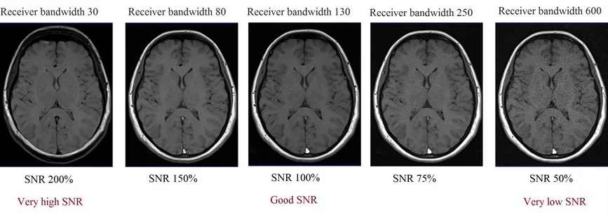
Receiver bandwidth is one of the parameters you can adjust on most scanners. Bandwidth and sampling time are inversely proportional: increasing the bandwidth shortens the sampling time but reduces the signal amplitude and increases the noise level in pixels, resulting in a significant reduction in the signal-to-noise ratio (SNR) of the image.
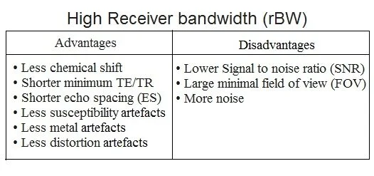
Practical applications of high receiver bandwidth (rBW)
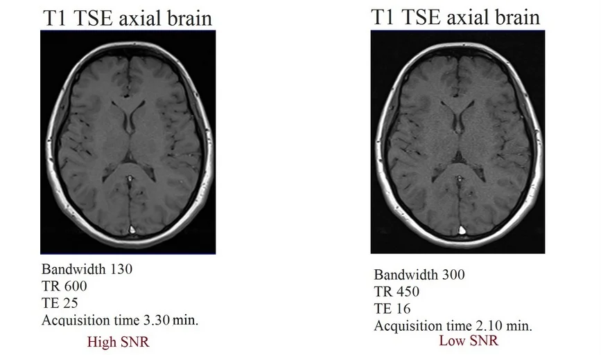
Increasing the receiver bandwidth shortens the scan time by allowing shorter TR and TEs. For example, a T1 sequence with a bandwidth of 130, a TR of 600, and a TE of 25 is usually acquired in about 3.30 minutes. However, using the same sequence with a bandwidth of 300 enables you to reduce the minimum TR to 450 and TE to 16, thereby decreasing the scan time from 3.30 minutes to 2.10 minutes. This option can be particularly useful for scanning claustrophobic and moving patients. One potential drawback is that opting for a higher bandwidth results in a reduction in the signal-to-noise ratio (SNR).
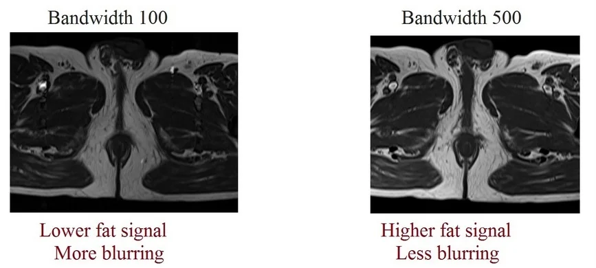
Increasing the receiver bandwidth can be a method to produce less blurry images since it reduces the echo spacing. In turbo spin echo sequences, a higher bandwidth increases the turbo factor because of the shorter echo spacing. This increase in the turbo factor leads to a higher fat signal in TSE scans.
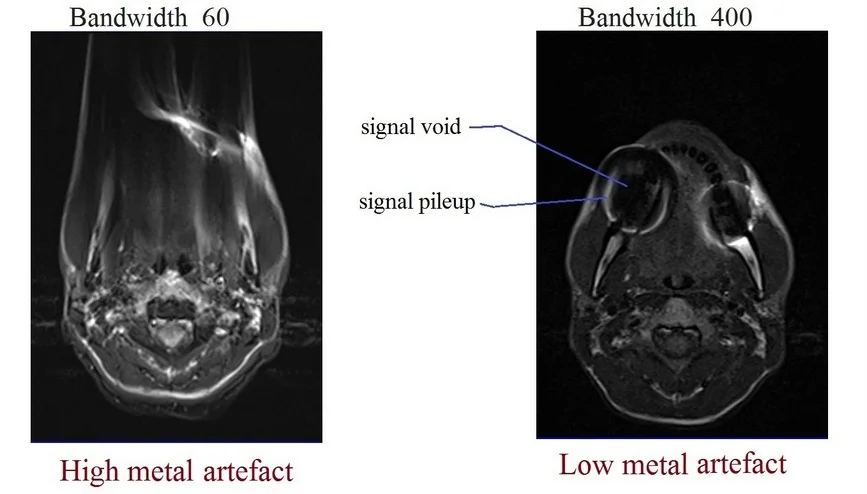
Higher receiver bandwidth sequences are also highly effective in reducing metallic susceptibility artifacts. The area around the implant undergoes manipulation due to strong local off-resonances, resulting in field distortions. The extent of these field distortions depends on the size, shape, and properties of the metal. During signal processing, these in-plane and through-plane distortions shift the image pixels from their actual positions, leading to a distorted image. Regions with pronounced field changes will result in signal voids and appear as black areas in the image. Conversely, regions with signal pileups will appear as very bright areas. Increasing the bandwidth reduces the through-plane distortion of the slice profile, resulting in less distorted final images.
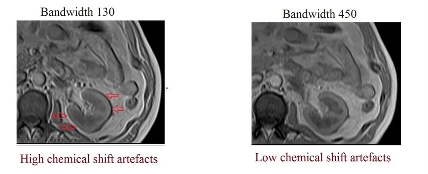
A higher receiver bandwidth also reduces chemical shift artifacts. Fat protons resonate at approximately 3.3 ppm lower frequency than water protons due to differences in their molecular structures. Signals from fat protons always shift to lower frequencies by a certain amount in the readout direction. This phenomenon is known as a chemical shift artifact. The degree of shifting depends on the bandwidth and field strength of the magnet. Increasing the receiver bandwidth will minimize chemical shift artifacts by reducing the shifting of fat protons. Higher field strengths increase the occurrence of chemical shift artifacts, which are commonly observed in 1.5T and 3T scanners.
Practical applications of low receiver bandwidth
Decreasing the bandwidth increases the SNR. This method can be used to boost the SNR in high-resolution scans with very small fields of view, such as temporomandibular joint (TMJ) imaging. However, reducing the bandwidth will increase the TR, TE, and echo spacing, resulting in longer scan times and a higher likelihood of chemical shift distortion and susceptibility artifacts.

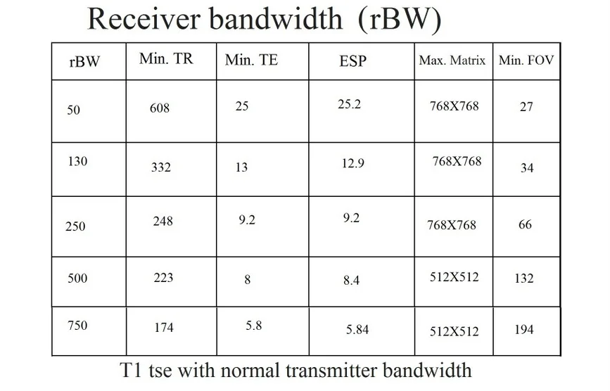
Lower receiver bandwidths will reduce the minimum field of view. For example, a sequence with a bandwidth of 250 will provide a minimum field of view of 130, whereas the same sequence with a bandwidth of 80 will decrease the minimum field to 90. This option can be used when scanning small body parts, such as TMJ and thumb imaging.

Receiver Bandwidth Manipulation
Bandwidth is one of the primary parameters that a Radiographer can manipulate to reduce scan time, increase SNR, and minimize artifacts. The following section will demonstrate how to adjust the bandwidth while maintaining SNR. To effectively manipulate the bandwidth, understanding its relationship with other parameters is essential. Radiographers can employ one of the following techniques to successfully control the bandwidth.
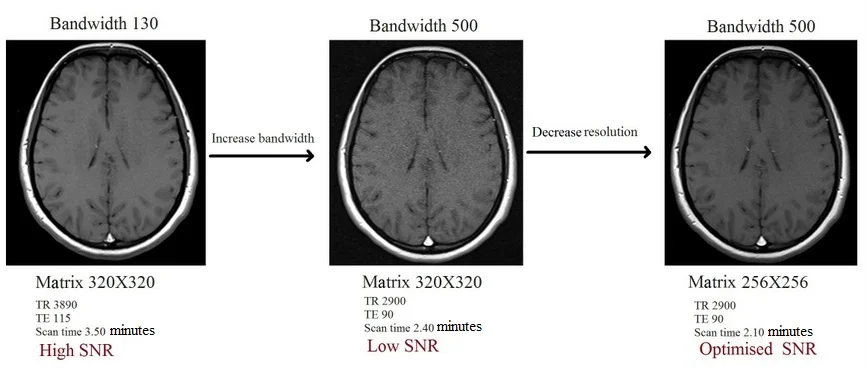
Bandwidth and Resolution
Both resolution and bandwidth utilize the readout gradient. The higher the resolution, the greater the readout gradient required. Similarly, a higher bandwidth necessitates a higher readout gradient. Increasing both bandwidth and resolution simultaneously amplifies the workload on the readout gradient, resulting in a significant drop in SNR and producing grainy images.
If you intend to enhance the bandwidth to reduce artifacts, it becomes necessary to compensate for the decreased SNR by adjusting other parameters. One of the key parameters that can be adjusted to improve SNR is the resolution. For instance, consider a T1 TSE sequence with a 200 FOV, 320×320 matrix, and a bandwidth of 130. When upgrading the bandwidth from 130 to 500, the signal will decrease from 100% to 49% of the original SNR. To counteract this signal reduction, you can reduce the matrix size from 320×320 to 256×256. This adjustment will elevate the signal from 49% to 85%, while also reducing the scanning time. The increased bandwidth empowers the user to further reduce TE and TR, consequently minimizing the scan time. This approach stands as one of the most effective means to significantly reduce scanning time with minimal compromise in quality. It proves especially time-efficient when scanning patients with metal implants, claustrophobia, or those who are prone to movement.
Bandwidth and averages (number of excitations NEX/number of signal averages NSA)
Increasing the bandwidth will reduce the SNR. The most appropriate technique for increasing SNR is to increase the number of averages. For example, consider a T1 TSE sequence with a bandwidth of 100, 2 averages, and a relative SNR of 100%. When the bandwidth is increased from 100 to 250, the SNR reduces to 74% of the original value. However, the signal loss can be compensated for by increasing the number of averages from 2 to 3. This method yields higher-quality images compared to the previous option. The downside of this approach is a significant increase in scan time. It is the most suitable technique to employ when time is not a critical factor.

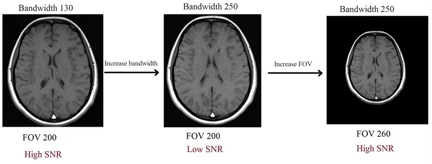
Bandwidth and field of view (FOV)
Increasing the field of view (FOV) will result in larger pixel sizes. Larger pixels can capture more signals and produce high signal-to-noise ratio (SNR) images. To counteract the SNR loss caused by the increased bandwidth, users can choose to increase the FOV. For instance, let’s consider a T1 turbo spin echo (TSE) sequence with a 200 FOV, a bandwidth of 130, and a relative SNR of 100%. When you increase the bandwidth from 130 to 250, the SNR decreases to 74%. However, by increasing the FOV from 200 to 260, you can restore the SNR to 100%. It’s important to note that this method may slightly reduce image quality, so it’s not the recommended approach when high-resolution scanning is required, such as in pituitary fossa imaging.
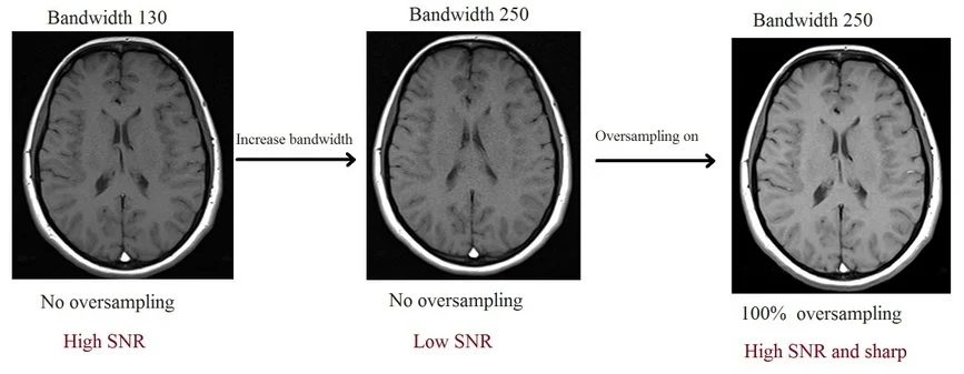
Bandwidth and oversampling
Increasing the oversampling will increase the SNR and reduce aliasing artifacts. This option can be used to enhance the SNR in small field of view scans with high bandwidth, such as prostate imaging. This method results in superior image quality. The only disadvantage of this approach is that the scan time will be extended.
References
Haacke EM, Brown RW, Thompson MR, Venkatesan R. Magnetic Resonance Imaging: Physical Principles and Sequence Design. John Wiley & Sons; 1999.
Edelman RR, Hesselink JR, Zlatkin MB, Crues JV. Clinical Magnetic Resonance Imaging. 3rd edition. Saunders; 2005.
Bernstein MA, King KF, Zhou XJ. Handbook of MRI Pulse Sequences. Academic Press; 2004.
Hoult DI, Richards RE. The signal-to-noise ratio of the nuclear magnetic resonance experiment. Journal of Magnetic Resonance (1969). 1976;24(1):71-85.