MRI Cardiac Perfusion
Indications for MRI cardiac perfusion scan
- For the assessment of blood flow after heart bypass surgery, angioplasty or artery stenting
- For the detection of microvascular dysfunction in various congenital heart diseases
- For the detection of ischemia before medical therapy or revascularization
- For the diagnosis and assessment of coronary artery disease (CAD)
- To identify the location and damage caused by a heart attack
- For the assessment of myocardial infarction complications
- For the assessment of cardiac masses
Heart anatomy and physiology
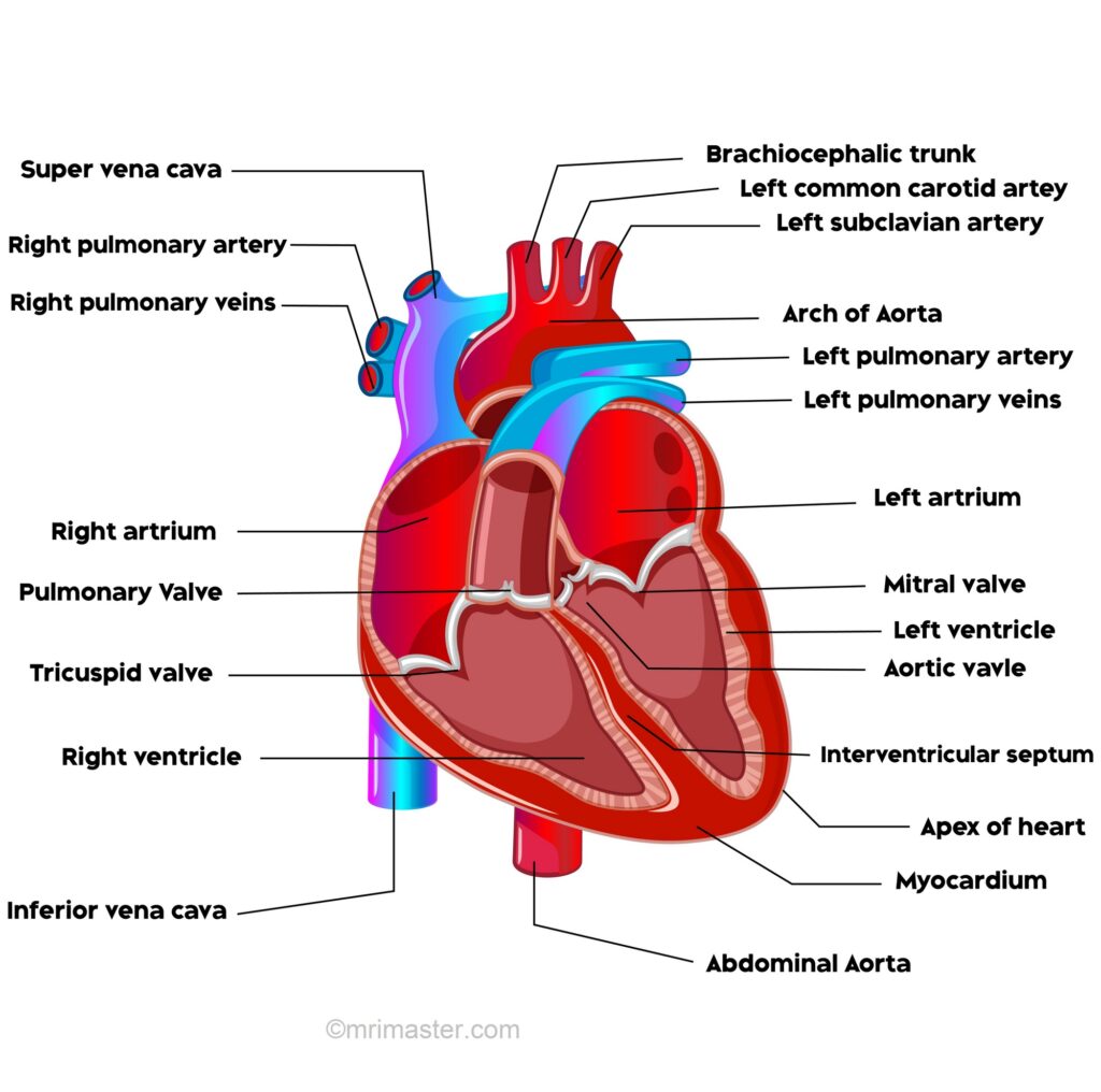
The heart is a muscular pump that receives deoxygenated blood and propels oxygenated blood to various parts of the body. It is composed of four chambers: the right atrium, right ventricle, left atrium, and left ventricle.
Blood flow through the heart
On the right side, deoxygenated blood from the superior and inferior vena cava enters the atrium while it is relaxed. At the same time, oxygenated blood from the pulmonary veins empties into the relaxed left atrium. The two atria then contract, forcing the blood into their respective relaxed ventricles. On the right side, deoxygenated blood flows through the right atrioventricular (tricuspid) valve, and on the left side, oxygenated blood flows through the left atrioventricular (bicuspid/mitral) valve.
Next, the ventricles contract, and the valves close. From the right ventricle, deoxygenated blood is forced through the semilunar (pulmonary) valve into the pulmonary trunk, and from the left ventricle, oxygenated blood is forced through the semilunar (aortic) valve into the aorta.
Valves
There are 4 valves of the heart:
1. The right atrioventricular valve/tricuspid valve separates the right atrium and right ventricle
2. The left atrioventricular valve/mitral valve separates the left atrium and left ventricle
3. The right semilunar/pulmonary valve lies between the right ventricle and pulmonary trunk
4. The left semilunar/aortic valve lies between the left ventricle and the aorta
Structure and function of the valves
The right atrioventricular valve, also known as the tricuspid valve, consists of three cusps. Similarly, the left atrioventricular valve, referred to as the bicuspid valve or mitral valve, is composed of two cusps. These valves open when the ventricles relax and close when the ventricles contract, effectively preventing the backflow of blood into the atria. The cusps of these valves always point into the ventricles, with their free edges attached to fibrous strands called chordae tendineae. These chordae tendineae, in turn, are connected to papillary muscles on the ventricular wall.
The semilunar valves are made up of three cusps each and serve the purpose of halting the blood from flowing back into the ventricles after a ventricular contraction. Positioned at the center of each valve is a fibrous nodule, and in the presence of increased back pressure, the cusps balloon outwards, causing their opposing surfaces to press together, effectively preventing any backflow.
Pericardium
The pericardium is a double walled sac that contains the heart and the roots of the great vessels. The pericardium is composed of three layers:
1. Fibrous pericardium is the outer layer which attaches to the diaphragm, vena cava, aorta and sternum
2. Parietal pericardium is the middle serous layer
3. Visceral pericardium forms the outer layer of the heart, the epicardium
The pericardial cavity lies between the parietal and visceral pericardium and contains serous fluid which acts to prevent friction during movements of the heart.
Layers of the heart
The heart is composed of three layers:
1. Epicardium is the outer layer of the heart formed by the visceral pericardium
2. Myocardium is the middle layer composed of cardiac muscle
3. Endocardium is the inner layer composed of simple squamous epithelium
Blood supply to the heart
The coronary arteries supply the myocardium and epicardium of the heart. The right and left coronary arteries arise from the ascending aorta.
The right coronary artery originates from the right aortic sinus and gives off two major branches. The marginal branch supplies blood to the right ventricle and atrium, while the posterior interventricular branch supplies blood to both ventricles.
The left coronary artery arises from the left aortic sinus and also gives off two significant branches. The anterior interventricular branch supplies blood to the walls of the ventricles, and the circumflex branch supplies blood to the left ventricle and atrium.
Venous drainage of the heart
Deoxygenated blood, which has supplied the heart itself, is carried by the cardiac veins. These veins follow a similar pathway to the coronary arteries. The four main cardiac veins are the great cardiac vein, anterior cardiac vein, middle cardiac vein, and posterior cardiac vein. These veins drain into the coronary sinus, which is the primary vein of the heart. The coronary sinus runs in the posterior atrioventricular groove and then opens into the right atrium.
Innervation of the heart
The sinoatrial (SA) node generates an electrical impulse that passes through the atrial musculature on both sides, causing them to contract. Atrial contraction leads to the discharge of blood into the relaxed ventricles. The electrical impulses eventually reach the atrioventricular (AV) node, situated in the interatrial septal region. From the AV node, these impulses travel onward through the atrioventricular bundle (bundle of His) and arrive at the interventricular septum. In the interventricular septum, the bundle divides into right and left bundle branches, which pass to their respective ventricles and send out many branches called Purkinje fibers. These Purkinje fibers carry and spread the electrical impulses, eventually causing the ventricles to contract.
Patient preparation prior to the appointment date
Instruct the patient to stop taking any products which contain caffeine 24 hours prior to their appointment. This is necessary as caffeine can interfere with the action of adenosine on the heart. Products containing caffeine include: coffee, tea, hot chocolate or drinks (Ovaltine, Horlicks) fizzy drinks (Lucozade, Lemonade, Iron Bru, Red Bull etc), certain ice-creams, some painkillers, even decaffeinated coffee.
Smokers must stop smoking or have nicotine 12 hours prior to their appointment as nicotine can increase the heart rate and invalidate the results of the test.
Instruct patients with asthma to avoid taking theophylline for 48 hours before the test. Asthma patients must bring their inhaler with them to their appointment.
Instruct the patients to stop taking the following medications 48 hours before the test:
Dipyridamole (Persantine, Aggrenox)
Erectile dysfunction medications
Stop taking the following medications on the day of the appointment:
Isosorbide dinitrate (e.g. Dilatrate, Isordil )
Isosorbide mononitrate (e.g. Imdur, ISMO, Monoket)
Nitroglycerin ( e.g., Minitran, Nitro patches, Nitrostat)
Beta Blockers ( e.g., metoprolol, metoprolol XL, atenolol)
Cardiac MRI technique
The most common challenge of cardiac MRI image acquisition is overcoming motion artifacts. Motion artifacts arising from the heart and lungs occur due to the cardiac cycle and the respiratory cycle. Respiratory motion can be eliminated by breath-holding or the respiratory navigator technique. Artifacts from cardiac motion, however, can only be eliminated by ECG gating. ECG gating acquires data during diastole when the heart is at rest.
Respiratory artefact reduction
The most commonly used techniques for eliminating respiratory artifacts are breath holding and respiratory navigation.
Breath holding technique
Cardiac scans are typically performed during expiration. This is because, during inspiration, there is an increased tendency for the diaphragm to move, leading to changes in anatomical positioning. Therefore, it is crucial to provide proper coaching to patients before placing them into the scanner.
- Instruct the patient to breathe in, but not too deeply.
- Instruct the patient to breathe out and then to stop breathing.
- Ask the patient to breathe normally after the scan (usually for under 20 minutes).
It is important that the patient inhales and exhales approximately the same amount of air during each breath-hold, as the position of the diaphragm is a crucial factor in ensuring reproducibility of anatomical positioning.
Navigator technique
The Navigator technique is used for patients who are unable to hold their breath. During free breathing, the motion of the diaphragm changes the position of the heart, greater vessels, and liver, leading to inconsistent image quality. This inconsistency arises because the same anatomical position is not identified for each sampled k-space point. A navigator consists of an intermittent two-dimensional pulse that excites a cylinder of spins, followed by a readout gradient in the direction of the long axis of the cylinder, acquiring a 1-dimensional profile of the area of interest.
The sequence utilizes a low flip angle (10) to minimize saturation. The abrupt change in signal intensity of the lungs and liver along the axis of the box is utilized to determine the diaphragm’s position. The navigator pulse lasts about 20ms and is executed every 200ms. A scan acceptance window is calculated from the preliminary pre-scan data, after which the actual scan acquisition commences.
The navigation box detects the diaphragm’s position during each slice acquisition, allowing imaging only when the diaphragm falls within the acceptance window.
ECG gating
Artifacts from cardiac motion can be suppressed using ECG (electrocardiographic) gating/triggering, where image acquisition is synchronized with the cardiac rhythm. This can be done with either prospective or retrospective triggering.
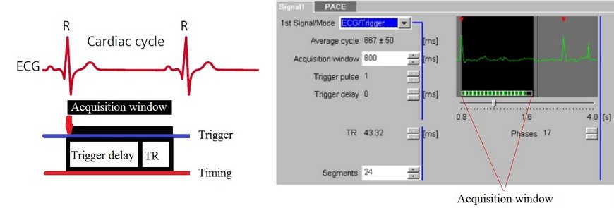
Prospective Triggering
This technique is most commonly used for single-slice or multi-slice single-phase cardiac imaging. Prospective triggering avoids cardiac motion artifacts by acquiring images when the heart is at rest during mid-diastole. Image acquisition is triggered after the R-peak and subsequently at the same stage in each R-R interval. Data acquired at phases other than the cardiac rest period may be degraded by motion artifacts.
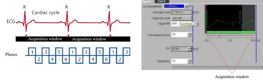
Retrospective Triggering
This method involves the continuous acquisition of data to produce images from all phases of the cardiac cycle in order to construct a cine movie. Images of myocardial contraction and relaxation can be used to detect myocardial dysfunction and perform cardiac chamber quantification.
In retrospective triggering, R-peaks are automatically detected, and data is acquired over an entire R-R interval for each specific K-profile. This process is repeated until all K-profiles are acquired. ECG data and acquisition timings are then matched during reconstruction to create images of all cardiac phases and assemble the cine scan.
Triggering parameters
Cardiac MRI technique
This interval is measured from one QRS complex peak to the next peak on an ECG scan. The number of slices that can be acquired in a single package depends on the RR interval. If more slices are required, the sequence can be acquired in two packages (i.e., 2 RR intervals).
Cardiac Frequency
The delay from detection of the R-peak to start of acquisition.
Trigger Delay
Cardiac scans are normally performed during expiration. This is because during inspiration, there is an increased tendency for the diaphragm to move, causing changes in anatomical positioning. Therefore, it is very important to provide proper coaching to the patients before placing them into the scanner.
RR Window
The RR window sets acceptable lower and upper limits for the RR-interval and determines the permitted percentage variation in the interval length. The lower limit of the RR-interval determines the fastest accepted heart rate, while the upper limit determines the slowest accepted rate. For example, with an RR window of 10 and 15, an acceptable RR interval ranges from 90% (110 minus 10%) to 115% (110 plus 15%)
Arrhythmia Rejection
Useful in cases of patients with marked cardiac arrhythmia. Data acquired outside the permitted R-R window is rejected. In prospective triggering, arrhythmia rejection skips two R-R intervals (i.e., one R-R interval after the irregular beat). The system then resumes data acquisition after the next R-peak.
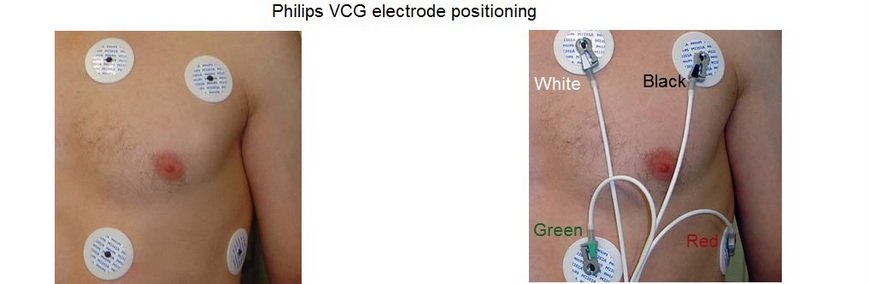
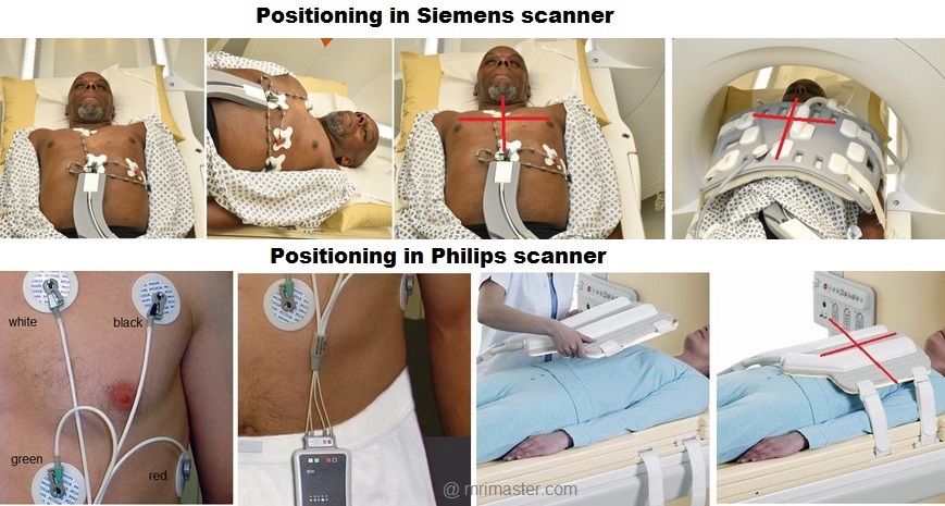
Positioning the electrodes in a Philips and GE scanner
The wireless VCG sensor has dual lead VCG monitoring capabilities based on
4 electrodes:
- Position the first electrode (green) approximately 1 cm left of the xiphoid.
- Position the second (white) and third (red) electrode to form a triangle around the nipple..The distance between the electrodes should be approximately 15 cm
- Position the fourth (black) electrode to the left of the top electrode, near the axilla.
Connect the green, white, red and black leads to the VCG electrodes as shown in the diagram.
Positioning the electrodes in a Siemens scanner
The wireless ECG sensor has a monitoring capability based on 3 electrodes:
- Position the first electrode (white) approximately 1 cm left of the sternal angle.
- Position the second (green), third (red), and fourth (black) electrode to form a triangle around the nipple. The distance between the electrodes should be approximately 5 to7 cm.
Connect the white, green, red and black leads to the ECG electrodes as shown in the diagram.
Warnings
Do not use the ECG signal for patient monitoring or diagnostic purposes.
Electrocardiograms acquired in the MR environment are useful only for cardiac triggered imaging. Such ECGs are NOT suitable for patient monitoring as the ECG signal is distorted when the patient is inside the magnet. ECG uses electrical measurements which can be corrupted by interference with electromagnetic fields and by magneto-hydrodynamic (MHD) effects.
Only use MR safe ECG electrodes.
Non MRI-safe ECG electrodes can cause severe skin burns.
Ensure proper ECG skin contact
A skin burn may develop if electrodes are not in complete contact with the skin. Ensure there are no air gaps and excess hair has been removed.
Do not use expired ECG electrodes.
Old electrodes can be dried out causing insufficient skin contact.
Do not reposition or reuse ECG electrodes.
Repositioning or the reuse of ECG electrodes may result in a heating effect due to worn down surfaces. Always use new electrodes.
Do not use paediatric ECG electrodes on adults and vice versa.
This may result in skin burns.
Do not place the ECG battery module directly on the patient’s skin.
This may result in skin burns.
Do not place the battery module close to the imaging volume.
Placing the battery close to the heart can lead to image artefacts and distortion
Contraindications for MRI
- Any electrically, magnetically or mechanically activated implant (e.g. cardiac pacemaker, insulin pump biostimulator, neurostimulator, cochlear implant, and hearing aids)
- Intracranial aneurysm clips (unless made of titanium)
- Pregnancy (risk vs benefit ratio to be assessed)
- Ferromagnetic surgical clips or staples
- Metallic foreign body in the eye
- Metal shrapnel or bullet
Preparing Patients for Cardiac Perfusion Scans in the Imaging Suite
- A satisfactory written consent form must be taken from the patient before entering the scanner room
- Ask the patient to remove all metal objects including keys, coins, wallet, cards with magnetic strips, jewellery, hearing aid and hairpins
- Ask the patient to undress and change into a hospital gown
- The patient must have cannulation in both arms: one cannula for the contrast injection must be a 16-gauge to accommodate a flow of 4-5 ml per second, and the other cannula for adenosine administration can be 18-20 gauge.
- Instruct the patient to hold their breath for the breath hold scans and breathe gently for the gated scans (its advisable to coach the patient two to three times before starting the scan)
- Request the patient to use the rest room before procedure
- Follow the appropriate manufacturer’s instructions for the ECG electrodes and the blue tooth receiver placement
- If the chest is covered with hair it is necessary to shave the required area before placing the ECG electrodes
- Thoroughly clean the ECG contact area with alcohol wipe
- Claustrophobic patients may be accompanied into the scanner room e.g. by staff member or relative with proper safety screening
- Offer headphones for communicating with the patient and ear protection
- Explain the procedure to the patient and answer questions
- Note the weight of the patient
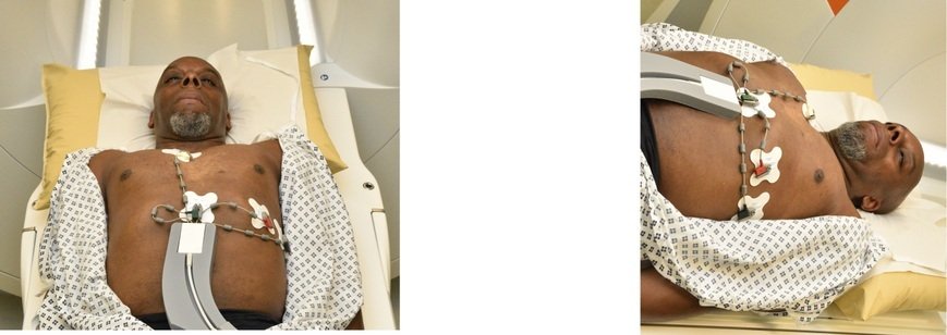
Positioning for MRI Cardiac Perfusion
- Position the patient in a supine position with head pointing towards the magnet (head first supine)
- Position the patient over the spine coil and connect the ECG electrodes as specified above and in accordance with the specific manufacturer’s instructions
- Check the quality of the ECG in the integrated ECG display on the scanner terminal. If the signal is not satisfactory and consistent, change the location of the electrodes
- Place the body coil or the dedicated cardiac coil over the chest
- Securely tighten the coil using straps to prevent respiratory artefacts
- Give cushions under the head and legs for extra comfort
- Centre the laser beam localiser over mid chest (i.e. over the nipples)
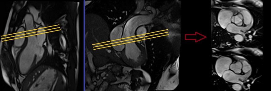
Recommended MRI Cardiac Perfusion Protocols and Planning
MRI Cardiac Perfusion Localiser
An initial three-plane SSFP (TrueFISP, B-FFE, or FIESTA) localizer scan is required for localization and sequence planning. These fast single-shot localizers have an acquisition time of under 25 seconds, making them excellent for localizing chest structures.
Cardiac planning localiser
Plan the axial localizer on the coronal plane and position the block across the chest as shown. The slices must cover the entire heart from the aortic arch to the diaphragm (usually 3-4 slices). Check the position in the other two planes.
Plan the sagittal localizer on the coronal plane and position the block parallel to the chest as demonstrated. The slices should encompass the entire heart from right to left (usually 3-4 slices). Verify the position in the other two planes.
Plan the coronal localizer on the axial plane and position the block across the chest as indicated. The slices must encompass the entire heart from the sternum to the thoracic aorta (usually 3-4 slices). Confirm the position in the other two planes.
All three blocks must be ISO-centered within the magnetic bore to avoid any inhomogeneity artifacts. These localizers are performed using a combination of ECG gating and breath-holding. Scans should be conducted during an expiratory breath-hold with an ECG trigger for every heartbeat (In our department, we instruct patients to take two breaths in and out before giving the “breathe out and hold” instruction).

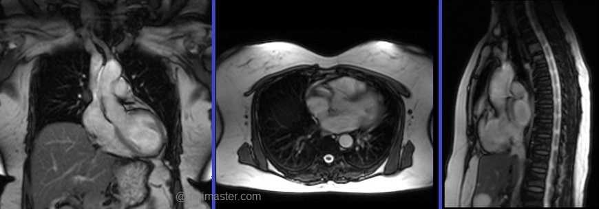
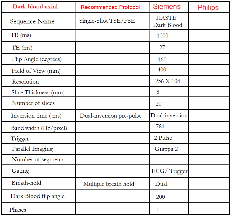
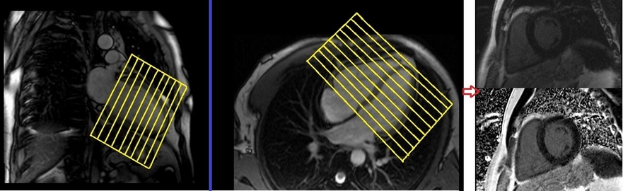
Dark or bight blood axial
Plan the axial T2 scans on the coronal localizer. Plan the planning block straight across the chest, as shown. Verify the positioning in the other two planes. An appropriate angle must be established in the sagittal plane (perpendicular to the thoracic spine). The number of slices should be sufficient to cover the heart from the aortic arch to the apex (usually 18-20 slices). These axial slices are acquired using a combination of ECG gating and breath-holds. Scans should be performed under expiratory breath-holds, with ECG triggers set for every second heartbeat. Axial bright blood scans involve a multiple breath-hold technique that acquires 8-10 slices with each breath hold. In our department, the cardiologist prefers conducting bright blood axials.

What are Dark Blood Sequences?
Dark blood sequences involve the use of a double preparation pulse. The signal from both blood and myocardium, both inside and outside the slice area, is inverted using the first pulse. Subsequently, a second pulse, known as a reinversion pulse, affects the signal within the measurement slice exclusively. As blood with an inverted signal flows into the measurement slice during data acquisition, it appears dark. To achieve this effect, data acquisition must be carried out during diastole. It is crucial for the reinversion and data acquisition to occur in the same position within the heart, ensuring successful reinversion of the tissues in the slice.
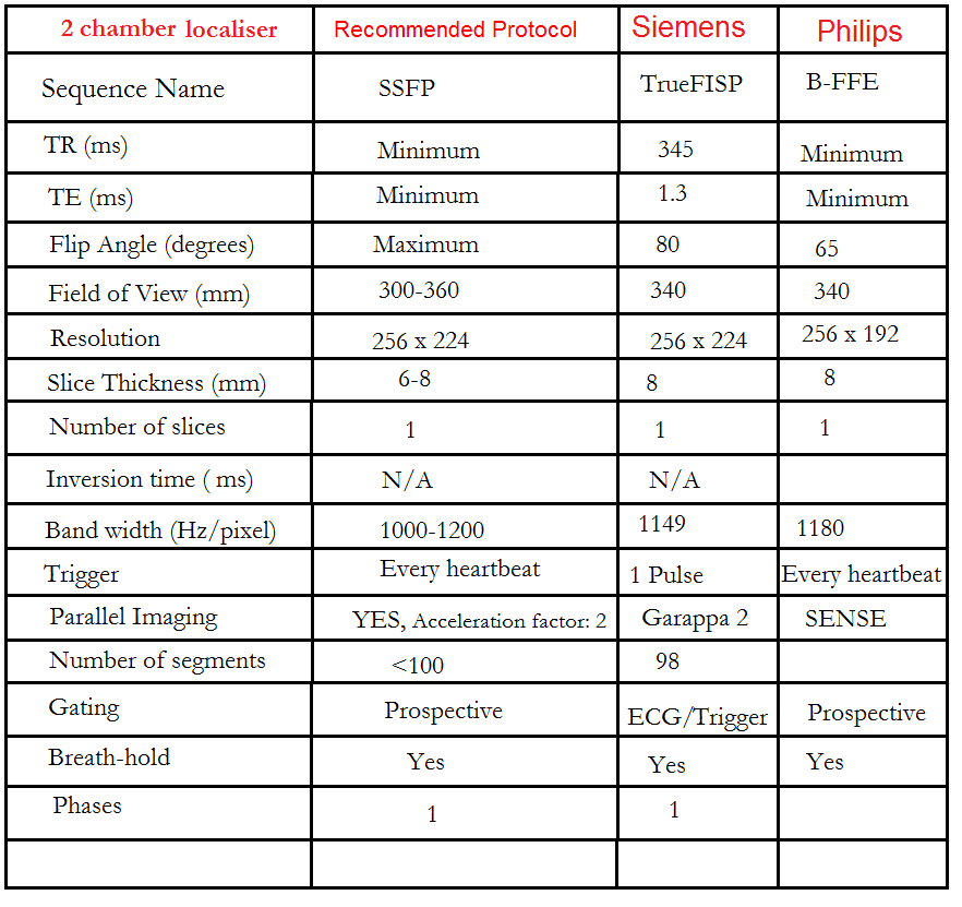
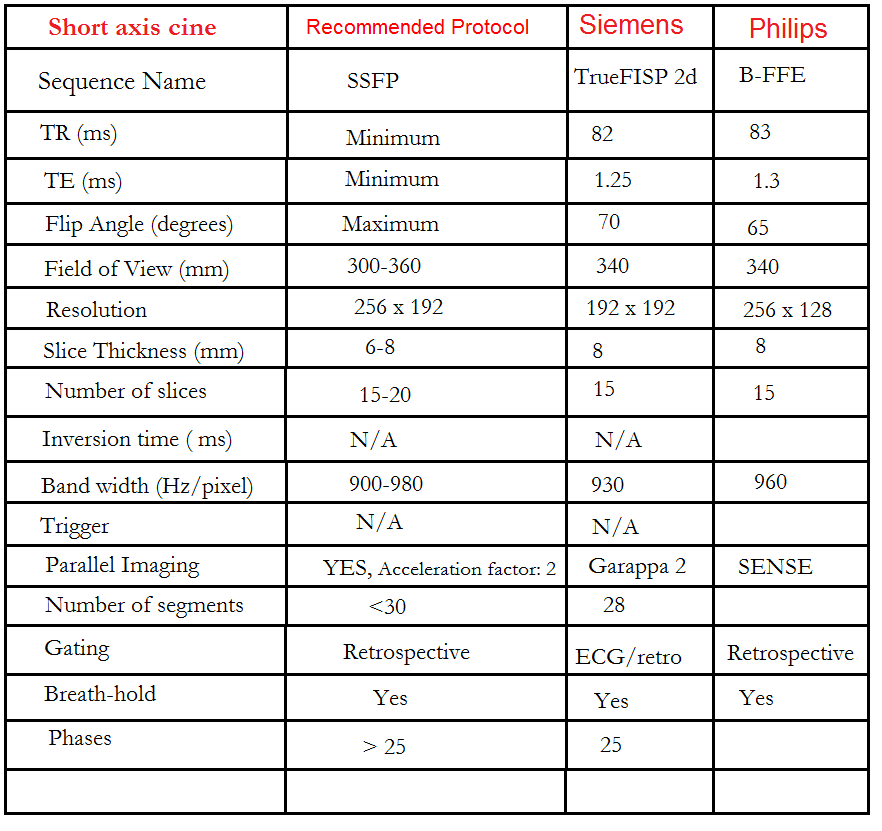
Recommended Protocol
Two chamber localiser
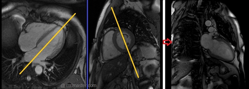
Plan the 2-chamber localizer on the axial plane and angle the planning block parallel to the interventricular septum. Move the position block to the center of the left ventricle, aligning it with the line along the center of the mitral valve and left ventricular apex. (Note: In most patients, these structures may not be visible in the same image; scroll through the axial images to identify both structures.) Verify the position in the other two planes. Provide an appropriate angle in the sagittal plane to maintain parallel alignment with the interventricular septum. This single-slice (non-cine) 2-chamber localizer is performed using a combination of ECG gating and breath-holding. Scans should be conducted during expiration breath-holds with an ECG trigger set for every heartbeat.

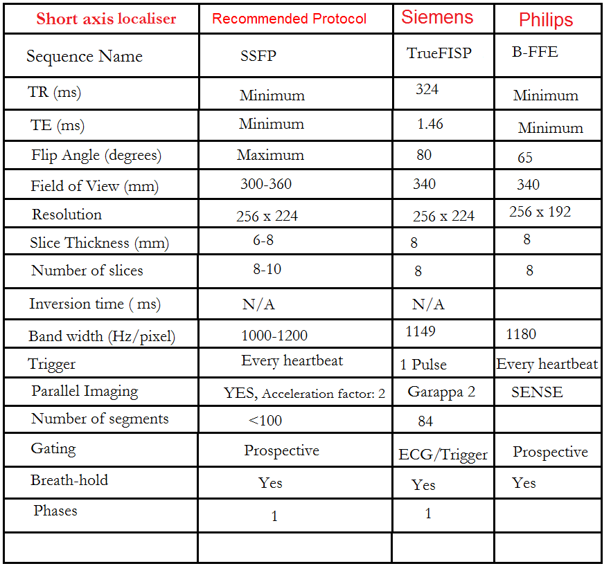
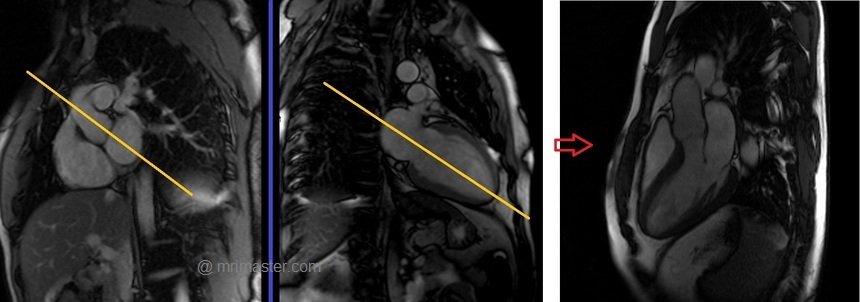
Recommended Protocol
Short axis localiser
Plan the short-axis localizer using the 2-chamber view as a reference, and orient the planning block perpendicular to the line running along the center of the mitral valve and the left ventricular apex, essentially perpendicular to the long axis of the left ventricle. Confirm the positioning in the other two planes as well. Provide an appropriate angle for the axial plane, which is perpendicular to the interventricular septum. Acquire slices that adequately cover the heart from the middle of the left atrium to the left ventricular apex; typically, 8-10 slices are needed. This multi-slice, non-cine short-axis localizer is conducted using a combination of ECG gating and breath-holding. Perform scans during expiration with breath-holding, triggering the ECG with each heartbeat.

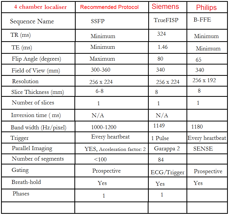
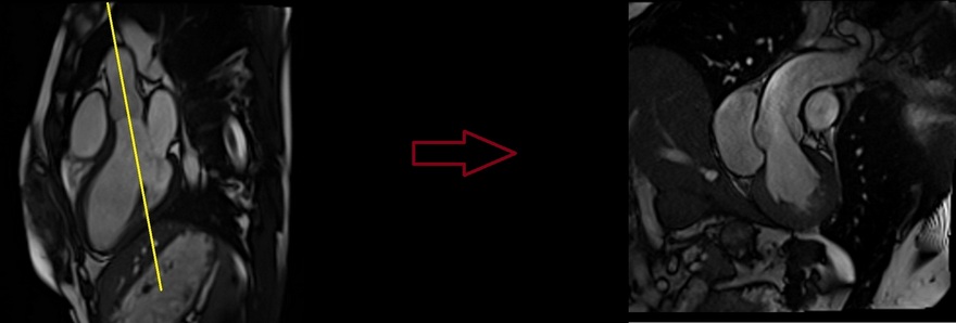
Recommended Protocol
Four chamber view localiser
Plan the 4-chamber localizer scan using the 2-chamber localizer image as a reference. Angle the planning block parallel to the line running along the center of the mitral valve and the left ventricular apex. Verify the position in the other two planes. Ensure an appropriate angle is set for the short-axis localizer, aligning it parallel to the line along the right ventricular apex and the left anterolateral papillary muscle. While planning in the short-axis localizer, take care to avoid the aorta in the resulting 4-chamber view (refer to the planning diagram for accurate guidance). This single-slice, non-cine 4-chamber localizer is conducted using a combination of ECG gating and breath-holding. Perform scans during expiration breath-holds with ECG triggering for every heartbeat.


Recommended Protocol
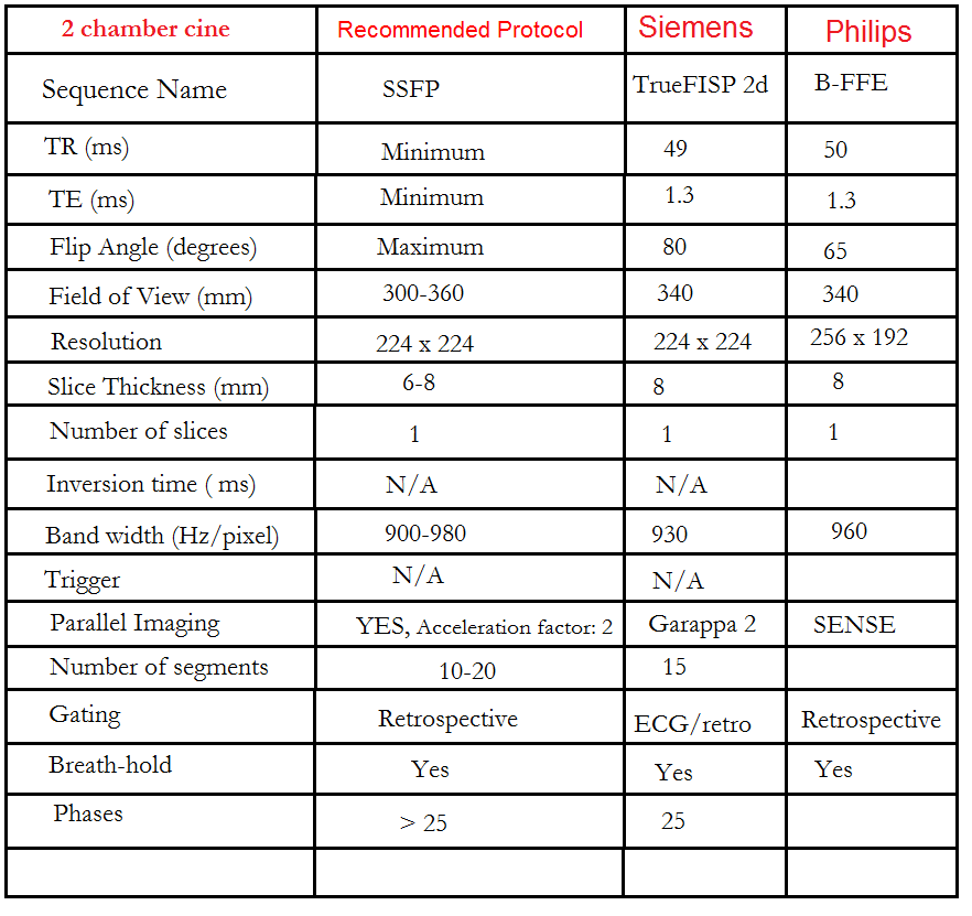
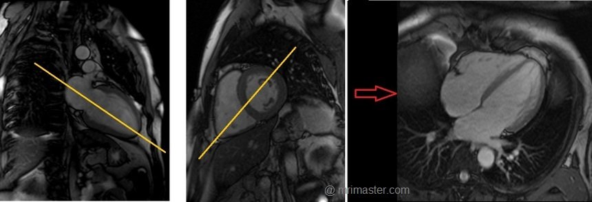
Left two chamber cine
Plan the 2-chamber cine sequence on the 4-chamber localizer and align the planning block parallel to the interventricular septum. Move the position block to the center of the left ventricle, parallel to the line along the center of the mitral valve and the left ventricular apex. Check the position in the other two planes. Ensure an appropriate angle is set in the short-axis localizer (parallel to the interventricular septum). This retrospective 2-chamber cine scan is performed with a combination of ECG gating and breath-holds. Scans should be conducted under expiratory breath-hold.
What are cine Sequences?
Cine sequences are employed to assess cardiac function. During cine acquisition, multiple individual images are captured at various phases of the cardiac cycle. These images are then played as a video, providing users with a visual representation of cardiac activity. TrueFISP sequences are strongly recommended for cine imaging due to their high temporal and spatial resolution, as well as improved blood-tissue contrast. In cardiac cine imaging, TrueFISP is combined with i-pat technology to reduce acquisition time.
Recommended Protocol
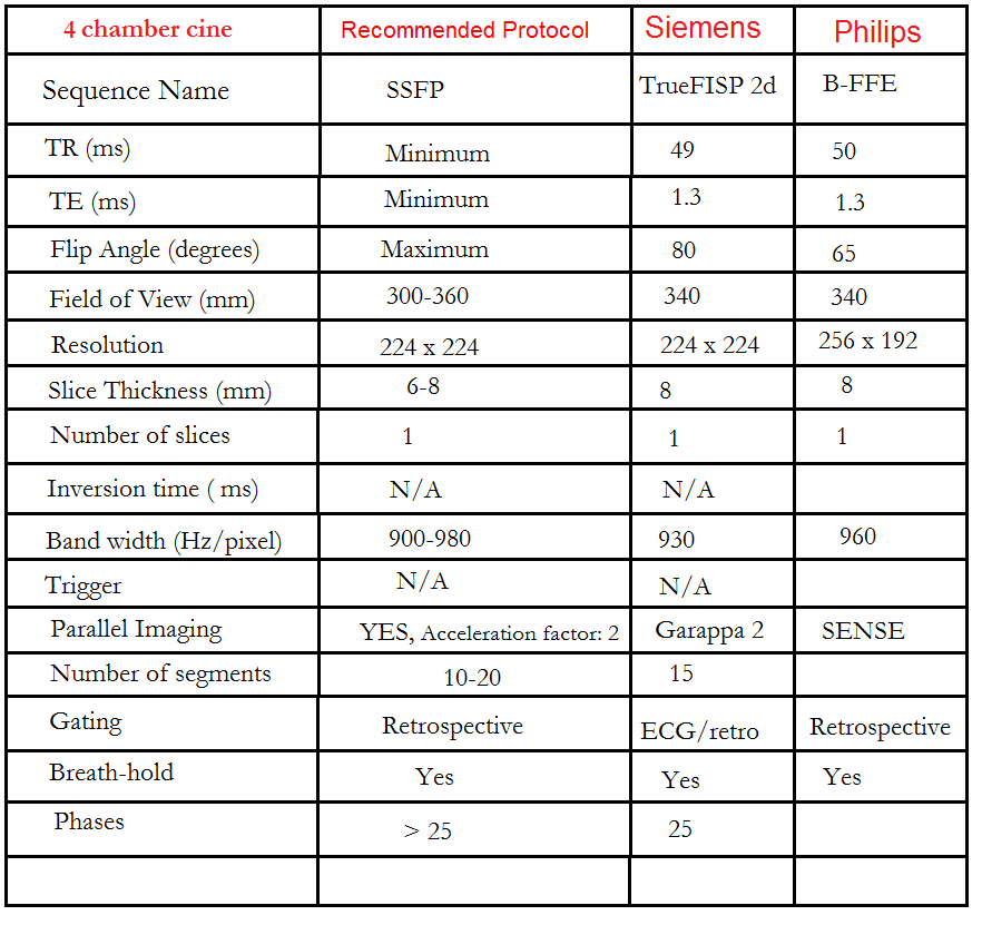
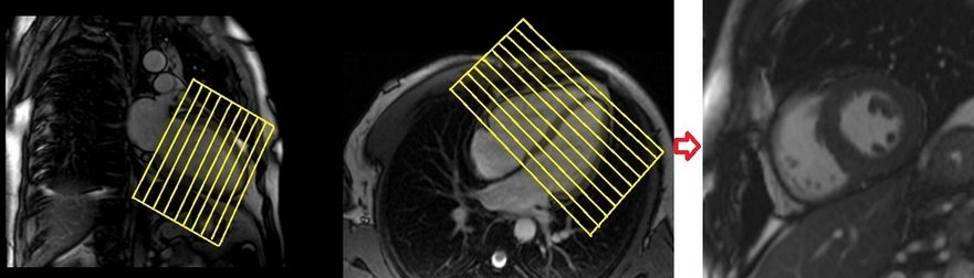
Four chamber cine
Plan the 4-chamber cine on the 2-chamber localizer and angle the planning block parallel to the line along the center of the mitral valve and left ventricular apex. Check the position in the other two planes. An appropriate angle must be given in the short-axis localizer (parallel to the line along the right ventricular apex and anterolateral papillary muscle).
While planning in the short-axis localizer, care should be taken to avoid the aorta in the resulting 4-chamber view (please refer to the planning diagram for appropriate guidance). This retrospective 4-chamber cine scan is performed with a combination of ECG gating and breath-holds. Scans should be conducted under expiratory breath-holds.
Recommended Protocol
Short axis cine
Plan the short-axis cine scans on the two-chamber cine view and angle the planning block perpendicular to the line along the center of the mitral valve and the left ventricular apex (i.e., perpendicular to the long axis of the left ventricle). Check the positioning in the other two planes as well. An appropriate angle must be chosen for the four-chamber cine view (perpendicular to the interventricular septum). The slices should be sufficient to cover the heart from the mitral valve to the left ventricular apex (usually 11-15 slices). These multi-slice retrospective short-axis cine scans are performed using a combination of ECG gating and multiple breath-holds. The scans should be conducted during expiration breath-holds, with one slice acquired during each breath-hold. Short axis cine scans must be planned on the end- diastole (maximum ventricular expansion) slice on 2chamber and 4 chamber cine.
Recommended Protocol
Three chamber (Left Ventricular Outflow Tract LVOT)cine
Plan the 3-chamber cine on the short-axis localizer and angle the planning block parallel to the line along the center of the aortic valve and the left ventricle (i.e., perpendicular to the posterolateral left ventricle wall). Check the position in the other two planes. An appropriate angle must be given in the 2-chamber localizer (parallel to the line along the center of the mitral valve and the left ventricular apex). This retrospective 3-chamber cine scan is performed with a combination of ECG gating and breath-hold. Scans should be conducted under expiration breath-hold.
Recommended Protocol
Left Ventricular Outflow Tract coronal cine
Plan the Left Ventricular Outflow Tract coronal cine using the 3-chamber cine images. Angle the planning block parallel to the line along the center of the aortic valve and ascending aorta. The LVOT coronal scan is usually planned only in the 3-chamber view. If the manufacturer has a ‘perpendicular’ function in the planning tab, please use it to achieve more accurate planning. This retrospective Left Ventricular Outflow Tract coronal cine scan is performed using a combination of ECG gating and breath-holds. Scans should be conducted under expiration breath-hold
Recommended Protocol
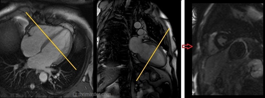
Aortic valve cine
Plan the aortic valve axial cine using the 3-chamber cine images as a reference. Angle the planning block parallel to the aortic annulus. Verify the position in the left ventricular outflow tract (LVOT) coronal cine. Ensure an appropriate angle is applied in the LVOT coronal cine, parallel to the aortic annulus. Utilize three slices to ensure comprehensive coverage of the aortic valve throughout the various phases of the cardiac cycle. This retrospective 3-chamber cine scan is conducted with a combination of ECG gating and breath-holds. Perform scans during expiration breath-holds for optimal results.
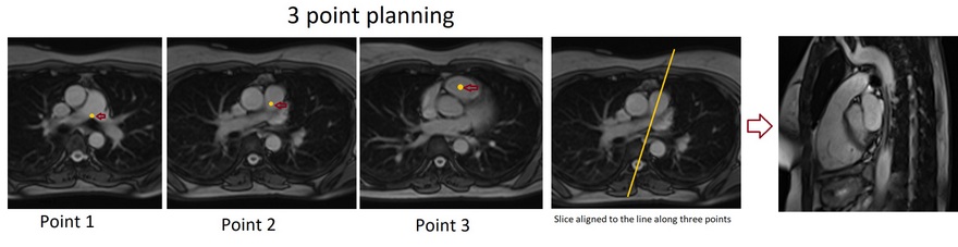
Right Ventricular Outflow Tract cine 3-point planning
Three-point planning is a software option made available by certain manufacturers. Three-point planning employs three distinct points in curved anatomy to achieve more accurate planning. The planning block will automatically align parallel to the designated points. Plan the cine for the Right Ventricular Outflow Tract on the axial bright blood images. Utilize the 3-point planner to establish the first point in the right atrium, the second point in the mid pulmonary trunk, and the third point at the pulmonary artery bifurcation. The planning block will then automatically align parallel to the right ventricular outflow tract. This retrospective coronal cine scan of the Right Ventricular Outflow Tract is performed with a combination of ECG gating and breath-hold. Scans should be conducted while maintaining an expiration breath-hold.
Recommended Protocol
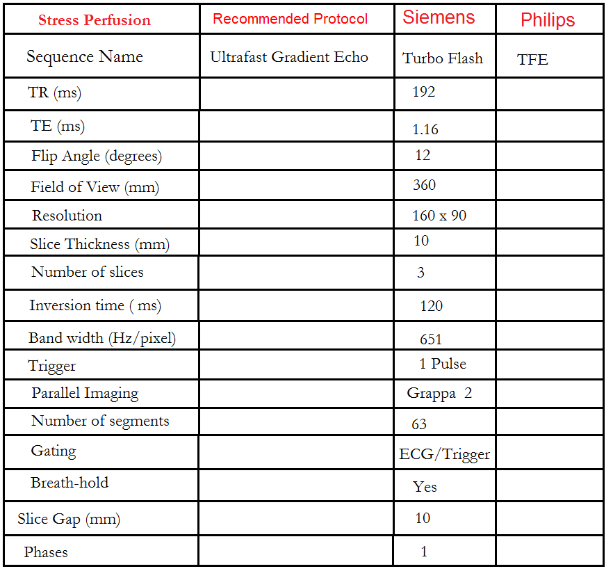
Stress Perfusion
Stress perfusion MRI can help detect ischemic heart disease, which involves an undersupply of blood and oxygen to the heart. Stress perfusion MRI involves injecting a contrast medium, where areas with good blood supply will be well-enhanced, while areas with ischemia are enhanced less effectively.
Blood flow (perfusion) to the heart can be assessed both at rest and under stress. Adenosine is injected during the stress test to simulate the effects of physical exertion. Once the contrast is administered, areas of the heart muscle with insufficient perfusion can be visualized. The rest test is usually performed afterward without adenosine and is used for comparison with images from the stress test.
Adenosine
Adenosine, the most commonly used vasodilator in cardiac imaging, promotes systemic arterial vasodilation during stress imaging of the heart by inducing myocardial ischemia. In a healthy patient, it increases coronary blood flow by four to five times the baseline value (0.8-1.2 ml min-1 g-1). Infusion of adenosine results in the vasodilation of non-stenotic coronary arteries, redistributing blood toward the non-stenotic region. The areas of restricted blood flow due to stenosis then become visible during the first pass of the contrast agent. For stress perfusion MRI, the recommended intravenous dose of adenosine is 140 mcg/kg/min, infused for 3-6 minutes (with a total maximum dose of 0.84 mg/kg). Adenosine has a very short half-life of less than 10 seconds; therefore, any side effects caused by adenosine are generally short-lived (usually under 2 minutes) and easily tolerated.
Contraindications
- Patients with known hypersensitivity to adenosine
- Patients with second- or third-degree heart block who do not have an artificial pacemaker
- Patients with sinus node disease, such as sick sinus syndrome or symptomatic bradycardia who
- Do not have an artificial pacemaker
- Patients with known bronchospastic or bronchoconstrictive lung disease (e.g. asthma)
Medications to avoid before using adenosine
- Beta-blockers, digoxin, diltiazem, or verapamil. These medications can increase the risk of an irregular heartbeat
- Carbamazepine or dipyridamole. These can increase the risk of adenosine's side effects
- Methylxanthines (eg. caffeine, theophylline, Aminophylline may decrease adenosine's effectiveness
Side effects of Adenosine
Most common:
- Abdominal pain or discomfort
- Throat, neck and jaw discomfort
- Facial flushing
- Mild headache
- Mild shortness of breath
- Chest tightness
- Palpitations
- Slow heartbeat
- Low blood pressure
- Light headedness
- Nervousness
- Nausea
Rare side effects:
- Asystole
- Ventricular Tachycardia
- Ongoing severe chest pain
- Heart attack
- Severe shortness of breath
- Death (1 in 10 000 patients
Stress Perfusion Scanning
Adenosine can be injected using an MRI-safe adenosine injector pump. In the absence of an MRI-safe pump, a normal adenosine injector pump can be placed outside the scanner room, and a long line can be run into the room. The dosage should then be adjusted according to the length and capacity of the tube (a 6m IV extension line will hold 12mm of fluid).
An initial test acquisition is carried out to ensure correct slice planning and is repeated as necessary to optimize image quality. Take care to avoid foldover artifacts. This first acquisition acts as a reference image for subsequent sequences.
Warn the patient of possible side effects and start the adenosine injection. Depending on the patient, heart rate usually rises after 30 seconds to one minute. Reassure the patient regarding possible symptoms of the adenosine injection. After 2 ½ minutes, give breath-hold instructions, begin scanning, and simultaneously inject contrast (0.5-1.0 mmol/kg at 4 ml/s). As adenosine has a short half-life, the patient’s heart rate should begin to drop after approximately 30 seconds. Gadovist is the preferred contrast agent used in cardiac MRI studies.
Stress Perfusion 3 out of 5 planning technique
Perfusion Planning is conducted within the short-axis plane, and the protocol consists of three slices. The initial slice is positioned at the apex, the second one at the mid-myocardium, and the final slice is targeted at the base of the ventricle. It is crucial to maintain an equal gap between these three slices. To enhance the precision of myocardial mapping planning, the 3 out of 5 planning technique has been introduced.
The 3 out of 5 planning method involves employing five slices initially, all with an identical slice gap, to comprehensively cover the entire ventricle in an end-diastolic phase. Users can subsequently reduce the number of slices to three, effectively eliminating one slice at the apex and one at the base. By adopting this technique, it ensures that the short-axis slices are meticulously positioned over the myocardium with the appropriate gap between them, facilitating accurate mapping.

Using the 3-out-of-5 planning technique, plan the short-axis slices based on the 2-chamber cine and position the block perpendicular to a line running through the center of the mitral valve and the left ventricular apex (i.e., perpendicular to the long axis of the left ventricle). Check the position in the other two planes. An appropriate angle must be established in the 4-chamber cine, perpendicular to the interventricular septum. While planning the five slices, adjust the slice gap to cover the entire ventricle, then reduce the number of slices to three. This turboflash dynamic short-axis cine is performed with ECG gating and breath-hold. Scans should be conducted during an expiration breath-hold with an ECG trigger on every heartbeat. Start the breath-hold during the early phase of the scan. Typically, 50 measurements are used to analyze the full contrast flow within the ventricles.

Recommended Protocol
Rest perfusion
The same planning and quantity of contrast as the stress test should be used for the rest test. The only difference is that the intravenous adenosine injection is not required for the rest perfusion test.
Note: If the stress test is normal, the rest test need not be carried out.
DELAYED SCANS (8-10 MINUTES POST GADOLINIUM)
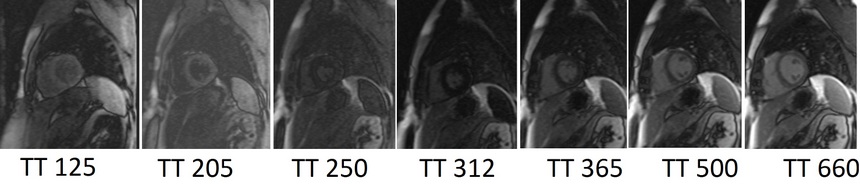
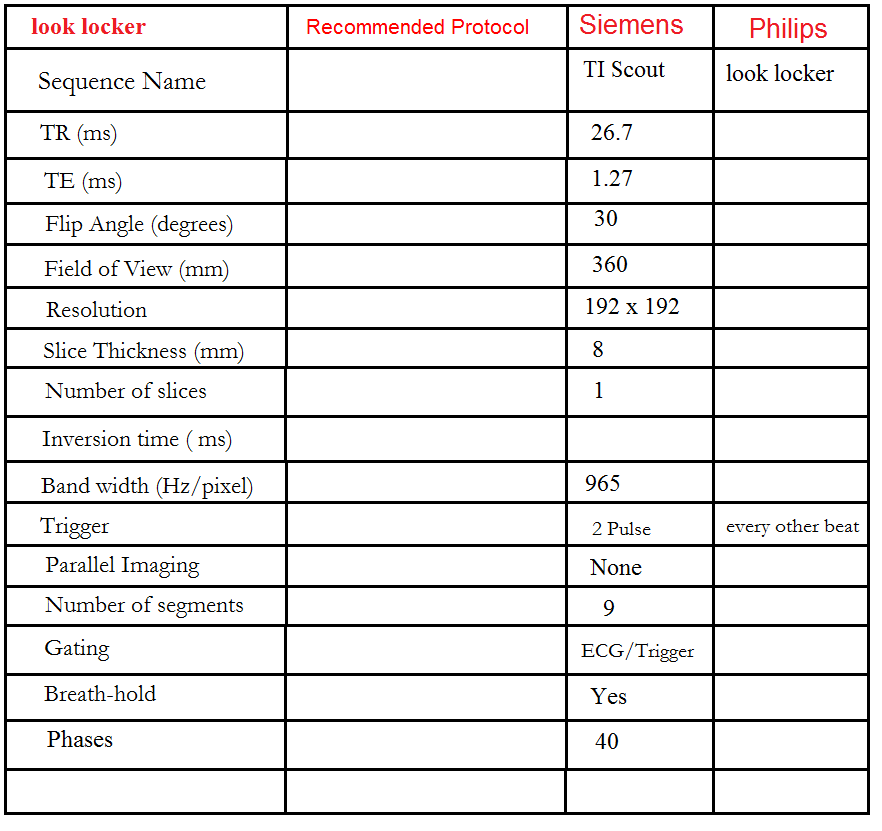
Look locker (TI scout)
This TI scout consists of a centrically ordered, segmented K-space inversion recovery gradient echo pulse sequence obtained over 2-3 heartbeats. Each segment corresponds to a different TI value. The aim is to determine the optimal TI value to nullify the signal from normal myocardium. Images are usually acquired with TI values ranging from 185 to 515 ms and are visually assessed by radiographers. These optimal TI values are then used for the subsequent delayed scans. In images with an optimal TI value, the signal intensity of normal myocardium will be nearly null, and the signal intensity of the left ventricular cavity will be lower than that of the infarcted region. Incorrect selection of the optimal null time can result in lower contrast and may reduce the visibility of the hyper-enhanced area, leading to an underestimation of the extent of infarction.
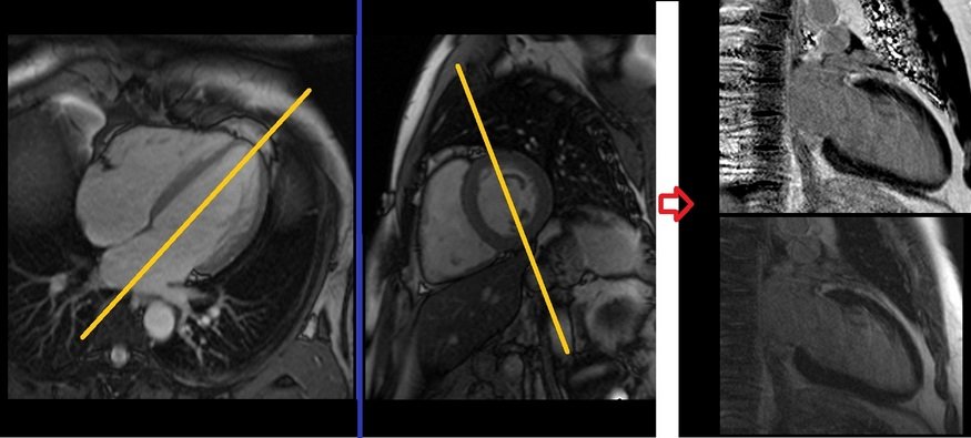
Look locker (TI scout) planning
Plan the Look-Locker axial sequence on the 4-chamber localizer. Angle the planning block perpendicular to the interventricular septum and move the position block to the middle of the ventricles. Check the position in the other two planes. An appropriate angle must be given in the 2-chamber localizer (perpendicular to the long axis of the left ventricle). This turbo field echo planar imaging (EPI) is performed with a combination of ECG gating and breath-holds. Scans should be conducted under expiration breath-holds with an ECG trigger on every second heartbeat (In our department, we instruct the patients to breathe in and out twice before the “breathe out and hold” instruction). This TI scout is acquired under a single breath-hold.
Recommended Protocol
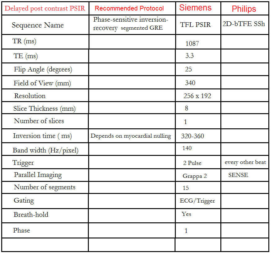
Phase sensitive inversion recovery (PSIR) scans
The PSIR Sequence is a 2D single-shot steady-state free precession (SSFP) image with phase-sensitive inversion recovery preparation. An appropriate TI value, chosen from the look locker, should be used to nullify the normal myocardium (usually 250-330 ms). This sequence provides both magnitude and real images.
Gadolinium washes in and out of the normal myocardium in a matter of minutes. Contrast normally accumulates in the extracellular space and will collect in areas of infarct with fibrous tissue. Inflammation or infiltration in the myocardium with accompanying edema will also be visualized as contrast collects in this extracellular space. The areas of delayed enhancement in the image indicate infarction or inflammation.
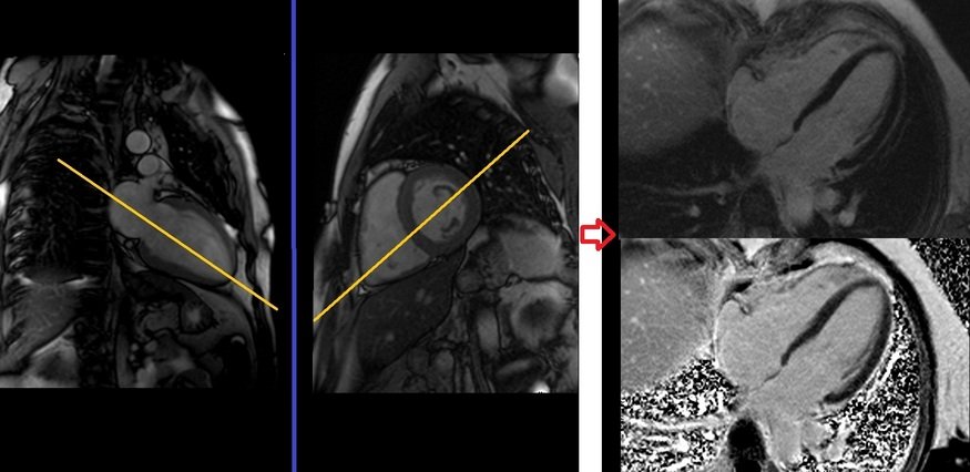
Delayed PSIR two chamber view planning
Plan the 2-chamber Phase-Sensitive Inversion Recovery (PSIR) scans on the 4-chamber localizer and angle the planning block parallel to the interventricular septum. Move the position block to the center of the left ventricle, parallel to the line along the center of the mitral valve and left ventricular apex. Check the position in the other two planes. An appropriate angle must be given in the short-axis localizer (parallel to the interventricular septum). This single-slice 2-chamber PSIR scan is performed with a combination of ECG gating and breath-hold. Scans should be performed under expiration breath-hold with an ECG trigger on every second heartbeat.
Recommended Protocol
Delayed PSIR four chamber view planning
Plan the 4-chamber Phase-Sensitive Inversion Recovery (PSIR) scans on the 2-chamber localizer and angle the planning block parallel to the line along the center of the mitral valve and left ventricular apex. Check the position in the other two planes. An appropriate angle must be given in the short-axis localizer (parallel to the line along the right ventricular apex and anterolateral papillary muscle). While planning in the short-axis localizer, care should be taken to avoid the aorta in the resulting 4-chamber view (please refer to the planning diagram for appropriate guidance). This single-slice 4-chamber PSIR scan is performed with a combination of ECG gating and breath-hold. Scans should be conducted under expiration breath-hold with an ECG trigger on every second heartbeat.
Delayed PSIR short axis view planning
Plan the short-axis Phase-Sensitive Inversion Recovery (PSIR) scans on the 2-chamber cine and angle the planning block perpendicular to the line along the center of the mitral valve and left ventricular apex (i.e., perpendicular to the long axis of the left ventricle). Check the position in the other two planes. An appropriate angle must be given in the four-chamber cine (perpendicular to the interventricular septum). Slices must be sufficient to cover the heart from the mitral valve to the left ventricular apex (usually 8-12 slices). These multi-slice short-axis PSIR scans are performed with a combination of ECG gating and breath-hold. Scans should be conducted under an expiration breath-hold with an ECG trigger on every second heartbeat. Short-axis cine scans must be planned on the end-diastole (maximum ventricular expansion) slice on the 2-chamber and 4-chamber cine.
Recommended Protocol
CLICK THE SEQUENCES BELOW TO CHECK THE SCANS
-
Trufi_Localiser1
-
Trufi_Localiser_3plane_Trigger2
-
Haste_20 slice_axial_dark blood3
-
Trufi_2 Chamber_Localiser4
-
Trufi_Short Axis_Localiser5
-
Trufi_4 Chamber_Localiser6
-
Left Ventricular (LV) Function

-
Trufi 2D_Retro_2 Chamber_Cine7
-
Trufi 2D_Retro_4 Chamber_Cine8
-
Trufi 2D_Retro_Short Axis_Cine9
-
Trufi 2D_Retro_3 Chamber_Cine10
-
Adenosine Stress Perfusion
-
TFL_SHORT AXIS_DYNA_STRESS11
-
TFL_SHORT AXIS_DYNA_REST12
-
TI SCOUT (10 minutes post gadolinium)13
-
TFL_T1_PSIR_TWO CHAMBER14
-
TFL_T1_PSIR_FOUR CHAMBER15
-
TFL_T1_PSIR_SHORT AXIS16