Lumbar Spine Exit foramen View
Indications for mri lumbar spine exit foramen view
- Arteriovenous malformation (AVM)
- Exit forearm neuroma
- Exit forearm tumors
- Disc sequestration
Note:-The MRI of the lumbar spine exit foramen view is typically conducted as an extra or subsequent scan to the lumbar spine MRI. This is done when there is a suspected issue located in the exit foramen, which is not well visualized in the standard lumbar spine MRI images.
Contraindications
- Any electrically, magnetically or mechanically activated implant (e.g. cardiac pacemaker, insulin pump biostimulator, neurostimulator, cochlear implant, and hearing aids)
- Intracranial aneurysm clips (unless made of titanium)
- Pregnancy (risk vs benefit ratio to be assessed)
- Ferromagnetic surgical clips or staples
- Metallic foreign body in the eye
- Metal shrapnel or bullet
Patient preparation
- A satisfactory written consent form must be taken from the patient before entering the scanner room
- Ask the patient to remove all metal objects including keys, coins, wallet, cards with magnetic strips, jewellery, hearing aid and hairpins
- If possible provide a chaperone for claustrophobic patients (e.g. relative or staff )
- Contrast injection risk and benefits must be explained to the patient before the scan
- Gadolinium should only be given to the patient if GFR is > 30
- Offer earplugs or headphones, possibly with music for extra comfort
- Explain the procedure to the patient
- Instruct the patient to keep still
- Note the weight of the patient
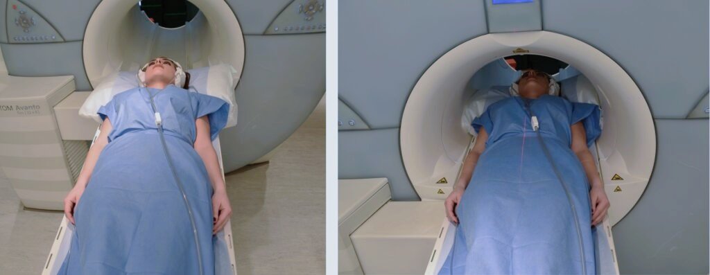
Positioning
- Head first supine
- Position the paient in the spine coil and immobilise with cushions
- Give cushions under the legs for extra comfort
- Centre the laser beam localiser over the mid abdomen (4 inches above the iliac crest)
Recommended MRI Lumbar Spine Exit Foramen View Protocols and Planning
localizer
A three-plane localizer must be taken at the beginning to localize and plan the sequences. Localizers are normally less than 25 seconds, and they consist of T2\T1 weighted low-resolution scans.

T2 tse sagittal 3mm
Plan the sagittal slices on the coronal plane and angle the position block parallel to the spinal cord. Check the positioning block in the other two planes, ensuring an appropriate angle is given in the axial plane (parallel to the center of the vertebral body and the spinous process). Verify the position block in the sagittal plane, ensuring the field of view (FOV) is big enough to cover the entire lumbar and sacral spine from T11 down to the coccyx (normally 350mm).
The slices should be sufficient to cover the spine from the lateral border of the right transverse process up to the lateral border of the left transverse process. To prevent peristalsis and breathing artifacts over the spinal area, place a saturation band over the abdomen (in front of the aorta) in the sagittal plane. Additionally, set the phase direction from head to feet to minimize further motion artifacts from the abdomen.

Parameters
TR 3000-4000 | TE 100-120 | SLICE 4MM | FLIP 130-150 | PHASE H>F | MATRIX 448X384 | FOV 350-350 | GAP 10% | NEX(AVRAGE) 2 |
T2 TSE Axial multi block and multi angle
Plan the axial blocks on the sagittal plane: angle the first position block parallel to the L5-S1 intervertebral disc, the second position block parallel to the L4-L5 intervertebral disc, and the third position block parallel to the L3-L4 intervertebral disc (only three blocks are needed in a normal spine). Additional blocks must be taken in the presence of a prolapsed disc in any other levels.
An appropriate angle must be given in the coronal plane (parallel to the intervertebral disc space). Slices must be sufficient to cover the intervertebral discs (normally 5 slices for each disc space).
A saturation band must be placed over the abdomen (in front of the aorta) in the sagittal plane. This is to avoid peristalsis and breathing artifacts over the spinal area.
To prevent cross-talk artifacts, ensure that the blocks are not overlapping in the area of interest, particularly the spinal canal.

Parameters
TR 3000-4000 | TE 100-120 | SLICE 4 MM | FLIP 130-150 | PHASE A>P | MATRIX 320X320 | FOV 230-270 | GAP 10% | NEX(AVRAGE) 2 |
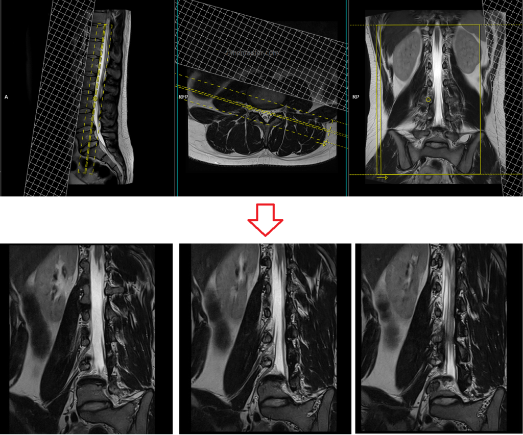
T2 TSE coronal oblique 2mm SFOV Right
Plan the right-side coronal oblique slices on the axial plane and align the planning block parallel to the exiting nerve roots. Verify the planning block in the other two planes. Apply an appropriate angle in the sagittal plane, parallel to the spinal canal. Ensure that the slices sufficiently cover the exit foramen from the lower facet to the posterior quarter of the vertebral body. Place a saturation band over the abdomen (in front of the block) in the axial plane. This is done to prevent breathing and vascular pulsation artifacts over the exit foramen area. Utilize a slice thickness of 2mm or less to achieve the best results.
Parameters
TR 3000-4000 | TE 90-120 | FLIP 150 | NEX 3 | SLICE 2 MM | MATRIX 320X320 | FOV 200-250 | PHASE R>L | GAP 10% | oversample 100% |
T2 TSE sagittal oblique 2mm SFOV Right
Plan the right-side sagittal oblique slices on the axial plane and align the planning block perpendicular to the exiting nerve roots. Verify the positioning of the planning block in the other two planes. Apply an appropriate angle in the coronal plane, keeping it parallel to the spinal canal. Ensure that the slices adequately cover the exit foramen from the medial quarter of the psoas muscle to the mid spinal canal. Place a saturation band over the abdomen (in front of the block) in the axial plane. This step is taken to prevent artifacts caused by breathing and vascular pulsations in the exit foramen area. Utilize a slice thickness of 2mm or less to achieve optimal results.

Parameters
TR 3000-4000 | TE 90-120 | FLIP 150 | NEX 3 | SLICE 2 MM | MATRIX 320X320 | FOV 200-250 | PHASE H>F | GAP 10% | oversample 100% |
T1 TSE sagittal oblique 2mm SFOV Right
Plan the right-side sagittal oblique slices on the axial plane and align the planning block perpendicular to the exiting nerve roots. Verify the positioning of the planning block in the other two planes. Apply an appropriate angle in the coronal plane, keeping it parallel to the spinal canal. Ensure that the slices adequately cover the exit foramen from the medial quarter of the psoas muscle to the mid spinal canal. Place a saturation band over the abdomen (in front of the block) in the axial plane. This step is taken to prevent artifacts caused by breathing and vascular pulsations in the exit foramen area. Utilize a slice thickness of 2mm or less to achieve optimal results.
Parameters
TR 400-500 | TE 15-20 | FLIP 150 | NEX 3 | SLICE 2 MM | MATRIX 320X320 | FOV 200-250 | PHASE H>F | GAP 10% | oversample 100% |
For contrast enhanced lumbar spine exit foramen view
Use T1 TSE fat-saturated coronal oblique and sagittal onlique sequences after the administration of IV gadolinium DTPA injection (copy the planning outlined above). The document below provides access to the recommended dosage of gadolinium DTPA injection, as advised by the manufacturer.
Planning for left side
T2 TSE coronal oblique 2mm SFOV Left
Plan the left-side coronal oblique slices on the axial plane and align the planning block parallel to the exiting nerve roots. Verify the planning block in the other two planes. Apply an appropriate angle in the sagittal plane, parallel to the spinal canal. Ensure that the slices sufficiently cover the exit foramen from the lower facet to the posterior quarter of the vertebral body. Place a saturation band over the abdomen (in front of the block) in the axial plane. This is done to prevent breathing and vascular pulsation artifacts over the exit foramen area. Utilize a slice thickness of 2mm or less to achieve the best results.

Parameters
TR 3000-4000 | TE 90-120 | FLIP 150 | NEX 3 | SLICE 2 MM | MATRIX 320X320 | FOV 200-250 | PHASE R>L | GAP 10% | oversample 100% |
T2 TSE sagittal oblique 2mm SFOV Left
Plan the left-side sagittal oblique slices on the axial plane and align the planning block perpendicular to the exiting nerve roots. Verify the positioning of the planning block in the other two planes. Apply an appropriate angle in the coronal plane, keeping it parallel to the spinal canal. Ensure that the slices adequately cover the exit foramen from the medial quarter of the psoas muscle to the mid spinal canal. Place a saturation band over the abdomen (in front of the block) in the axial plane. This step is taken to prevent artifacts caused by breathing and vascular pulsations in the exit foramen area. Utilize a slice thickness of 2mm or less to achieve optimal results.

Parameters
TR 3000-4000 | TE 90-120 | FLIP 150 | NEX 3 | SLICE 2 MM | MATRIX 320X320 | FOV 200-250 | PHASE H>F | GAP 10% | oversample 100% |