Whole Body DWI MRI Protocol and Planning
Introduction
Whole Body Magnetic Resonance Imaging (WB-MRI) with Diffusion-Weighted Imaging (DWI) is performed to comprehensively evaluate various medical conditions, including cancer, inflammation, and metastasis, by providing detailed information about tissue structure and function. It aids in:
Cancer Detection and Staging: WB-MRI-DWI is highly sensitive for detecting cancers throughout the body, aiding in early detection and accurate staging. It helps assess tumor size, location, and potential spread.
Metastasis Assessment: It’s valuable for detecting and characterizing metastases, enabling precise treatment planning and monitoring response.
Monitoring Treatment Response: WB-MRI-DWI tracks changes in tumor size, diffusion properties, and vascular patterns, facilitating assessment of treatment effectiveness.
Assessing Inflammatory and Infectious Diseases: WB-MRI-DWI can identify areas of inflammation, infection, or abscess formation, aiding in diagnosis and treatment planning.
Neurological Disorders: It’s useful in evaluating neurological conditions like multiple sclerosis, detecting lesions and monitoring disease progression.
Whole Body Evaluation: WB-MRI-DWI offers a holistic view of multiple body regions in a single examination, reducing the need for multiple scans.
Minimally Invasive Approaches: It can guide targeted biopsies and interventions by precisely locating abnormal tissue.
High-Risk Patient Screening: WB-MRI-DWI is suitable for high-risk individuals, such as those with known cancer predisposition, offering comprehensive screening.
Diffuse Diseases: It’s valuable for assessing diffuse diseases affecting multiple organs, like fibrosis or granulomatous diseases.
Research and Clinical Trials: WB-MRI-DWI aids in clinical research by providing non-invasive, detailed data for studying disease progression and treatment effects.
WB-MRI-DWI’s ability to provide whole-body insights, non-invasively and without ionizing radiation, makes it a powerful tool in diagnosing, staging, and monitoring various medical conditions.
Indications for Whole Body DWI MRI
- Assessing Inflammatory and Infectious Diseases
- Monitoring Treatment Response
- Cancer Detection and Staging
- Metastasis Assessment
- Whole Body Evaluation
- Preoperative Planning
Contraindications
- Any electrically, magnetically or mechanically activated implant (e.g. cardiac pacemaker, insulin pump biostimulator, neurostimulator, cochlear implant, and hearing aids)
- Intracranial aneurysm clips (unless made of titanium)
- Pregnancy (risk vs benefit ratio to be assessed)
- Ferromagnetic surgical clips or staples
- Metallic foreign body in the eye
- Metal shrapnel or bullet
Patient preparation for Whole Body DWI MRI
- A satisfactory written consent form must be taken from the patient before entering the scanner room
- Ask the patient to remove all metal objects including keys, coins, wallet, cards with magnetic strips, jewellery, hearing aid and hairpins
- Provide the patient with a thorough explanation of the process, including the duration, as this is a considerably lengthy procedure.
- Ask the patient to undress and change into a hospital gown
- If possible provide a chaperone for claustrophobic patients (e.g. relative or staff )
- Offer earplugs or headphones, possibly with music for extra comfort
- Instruct the patient to keep still
- Note the height and weight of the patient
Positioning for Whole Body DWI MRI
- Position the patient atop the spine coil and position the peripheral coil on the legs. Place the two body coils respectively over the abdomen and chest, while situating the head and neck coil over the head and neck region.
- Safely fasten the body and peripheral coils with straps to minimize respiratory artifacts.
- Position the laser beam locator precisely above the sternoclavicular junction.

Recommended Whole Body DWI MRI Protocols and Planning
3D localizer
To ensure precise localization and sequence planning, it is recommended to begin with a 3D localizer scan. These rapid, low-resolution volumetric localizers have an acquisition time of less than 25 seconds, making them ideal for accurately identifying whole-body structures in all three planes.
To achieve a complete whole-body localizer image during Whole Body Imaging, it’s crucial to establish the reference point (SC joint) and table movement in the protocol settings. To generate the comprehensive localizer image from our reference point, initiate a table movement of 310 towards the head. This action repositions the table to the vertex, marking the scan’s starting point. The total localizer length is approximately 1700mm, effectively encompassing the entire body for most patients.
T1 VIBE DIXON CORONAL 5MM multi block auto compose
Planning for whole-body imaging involves segmenting the body into blocks from head to toe, which are subsequently merged using software to generate a unified whole-body image. The scanning protocol incorporates these blocks with overlapping regions, and automatic fusion occurs post-acquisition. Users have the option to employ the group function for streamlined head-to-toe planning in the 3D whole-body localizer, or they can individually arrange and configure ungrouped blocks.
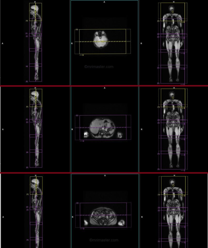
Plan the initial coronal block (head and neck) along the sagittal plane, positioning the block vertically across the head and neck as demonstrated. Verify the positioning block in the other two planes. Apply an appropriate axial plane angle (parallel to the right and left shoulder joints, perpendicular to the brain’s midline). Ensure slices encompass the head, neck, and upper chest, spanning from the anterior chest wall to the vertebrae’s spinous process. Maintain a sufficiently large Field of View (FOV) from vertebrae to mid-chest. To prevent wrap-around artifacts, employ phase oversampling. Direct the patient to hold their breath during image acquisition.
Now, move to the second block and ensure that the block is properly planned in the abdomen and chest. It should extend vertically across the abdomen in the sagittal plane and horizontally across the abdomen in the axial plane, providing coverage from skin to skin. This block is also performed under breath hold. All subsequent blocks are performed without breath hold.
Proceed by repeating the procedure for each remaining block, ensuring consistent parameters (slice count, angle, FOV, and thickness) across all blocks for seamless image composition.
Parameters
TR 6-7 | TE 2.39 4.77 | FLIP 10 | NXA 1 | SLICE 5 MM | MATRIX 512×384 | FOV 400-450 | PHASE R>L | OVERSAMPLE 30% | BH YES |
T2 STIR CORONAL 5MM multi block auto compose
Plan the initial coronal block (head and neck) along the sagittal plane, positioning the block vertically across the head and neck as demonstrated. Verify the positioning block in the other two planes. Apply an appropriate axial plane angle (parallel to the right and left shoulder joints, perpendicular to the brain’s midline). Ensure slices encompass the head, neck, and upper chest, spanning from the anterior chest wall to the vertebrae’s spinous process. Maintain a sufficiently large Field of View (FOV) from vertebrae to mid-chest. To prevent wrap-around artifacts, employ phase oversampling.
Now, move to the second block and ensure that the block is properly planned in the abdomen and chest. It should extend vertically across the abdomen in the sagittal plane and horizontally across the abdomen in the axial plane, providing coverage from skin to skin.
Proceed by repeating the procedure for each remaining block, ensuring consistent parameters (slice count, angle, FOV, and thickness) across all blocks for seamless image composition.
Parameters
TR 4000-6000 | TE 110 | FLIP 160 | NEX 1 | SLICE 5MM | MATRIX 384X384 | FOV 400-450 | PHASE R>L | GAP 10% | TI 150 |
STIR EPI DWI b50-b500-b1000 5MM free breathing coronal multi block auto compose
Plan the initial coronal block (head and neck) along the sagittal plane, positioning the block vertically across the head and neck as demonstrated. Verify the positioning block in the other two planes. Apply an appropriate axial plane angle (parallel to the right and left shoulder joints, perpendicular to the brain’s midline). Ensure slices encompass the head, neck, and upper chest, spanning from the anterior chest wall to the vertebrae’s spinous process. Maintain a sufficiently large Field of View (FOV) from vertebrae to mid-chest. To prevent wrap-around artifacts, employ phase oversampling.
Now, move to the second block and ensure that the block is properly planned in the abdomen and chest. It should extend vertically across the abdomen in the sagittal plane and horizontally across the abdomen in the axial plane, providing coverage from skin to skin.
Proceed by repeating the procedure for each remaining block, ensuring consistent parameters (slice count, angle, FOV, and thickness) across all blocks for seamless image composition.
Parameters
TR 6000-7000 | TE 90 | IPAT ON | NEX 2 3 5 | SLICE 5 MM | MATRIX 224X224 | FOV 400-450 | PHASE R>L | TI 150 | B VALUE 50 |
T1 TSE sagittal 4mm whole spine automatic composing
When using the auto-composing protocol, both the cervicothoracic and thoracolumbar blocks will appear on the 3D localizer. The planning should begin with the cervicothoracic block and once it is fully completed, move on to the thoracolumbar block. It is important to ensure sufficient overlap between the blocks. Once both blocks are planned, with proper positioning and alignment, the user can initiate the scan. After both scans are completed, the system will automatically compose the blocks and generate whole spine sagittal images.
For the cervicothoracic planning block, it should be planned on the coronal plane, and the positioning block should be angled parallel to the cervicothoracic spine. It is necessary to check the positioning block in the axial and sagittal planes. In the axial plane, the angle should be parallel to the line connecting the center of the vertebral body and the spinous process. In the sagittal plane, the field of view (FOV) should cover the cervicothoracic spine from 1 inch above C1 down to T11, typically ranging from 350-400 mm. The slices should adequately cover the spine from the lateral border of the right transverse process to the lateral border of the left transverse process. To avoid breathing artifacts over the spinal area, a saturation band should be placed over the chest in the sagittal plane, as depicted in the diagram. The phase direction should be head to feet to minimize motion artifacts from the chest.
Similarly, for the thoracolumbar planning block, it should be planned on the coronal plane, with the positioning block angled parallel to the thoracolumbar spine. The positioning block should be checked in the axial and sagittal planes, ensuring an appropriate angle parallel to the line connecting the center of the vertebral body and the spinous process in the axial plane. The sagittal plane FOV should cover the thoracolumbar spine from T7 down to the coccyx, typically ranging from 350-400 mm. The slices should sufficiently cover the spine from the lateral border of the right transverse process to the lateral border of the left transverse process. To prevent breathing artifacts, a saturation band should be placed over the abdomen in the sagittal plane, as shown in the diagram. The phase direction should be head to feet to minimize motion artifacts from the chest.

Parameters
TR 3000-5000 | TE 100-120 | SLICE 4MM | FLIP 130-150 | PHASE H>F | MATRIX 512X512 | FOV 350-400 | GAP 10% | NEX(AVRAGE) 2 |
T2 TSE STIR sagittal 4mm whole spine auto composing
When using the auto-composing protocol, both the cervicothoracic and thoracolumbar blocks will appear on the 3D localizer. The planning should begin with the cervicothoracic block and once it is fully completed, move on to the thoracolumbar block. It is important to ensure sufficient overlap between the blocks. Once both blocks are planned, with proper positioning and alignment, the user can initiate the scan. After both scans are completed, the system will automatically compose the blocks and generate whole spine sagittal images.
For the cervicothoracic planning block, it should be planned on the coronal plane, and the positioning block should be angled parallel to the cervicothoracic spine. It is necessary to check the positioning block in the axial and sagittal planes. In the axial plane, the angle should be parallel to the line connecting the center of the vertebral body and the spinous process. In the sagittal plane, the field of view (FOV) should cover the cervicothoracic spine from 1 inch above C1 down to T11, typically ranging from 350-400 mm. The slices should adequately cover the spine from the lateral border of the right transverse process to the lateral border of the left transverse process. To avoid breathing artifacts over the spinal area, a saturation band should be placed over the chest in the sagittal plane, as depicted in the diagram. The phase direction should be head to feet to minimize motion artifacts from the chest.
Similarly, for the thoracolumbar planning block, it should be planned on the coronal plane, with the positioning block angled parallel to the thoracolumbar spine. The positioning block should be checked in the axial and sagittal planes, ensuring an appropriate angle parallel to the line connecting the center of the vertebral body and the spinous process in the axial plane. The sagittal plane FOV should cover the thoracolumbar spine from T7 down to the coccyx, typically ranging from 350-400 mm. The slices should sufficiently cover the spine from the lateral border of the right transverse process to the lateral border of the left transverse process. To prevent breathing artifacts, a saturation band should be placed over the abdomen in the sagittal plane, as shown in the diagram. The phase direction should be head to feet to minimize motion artifacts from the chest.
Parameters
TR 4000-5000 | TE 110 | FLIP 130 | NEX 2 | SLICE 4MM | MATRIX 512X384 | FOV 350-400 | PHASE H>F | GAP 10% | TI 150 |
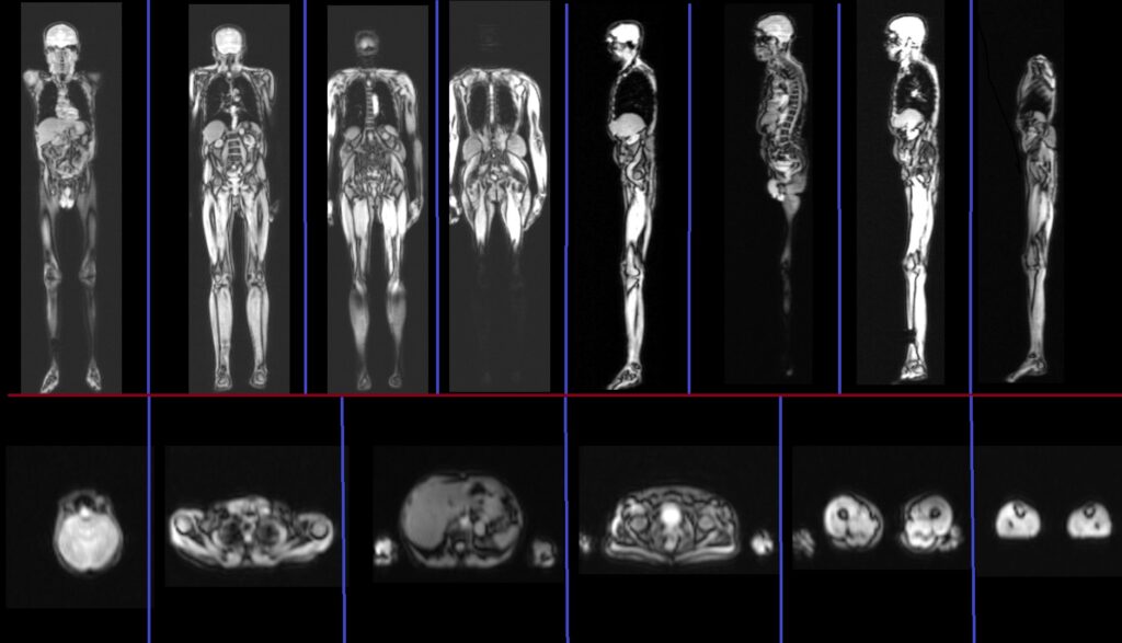
Image composing
Composing Siemens MRI refers to the capability of automatically or manually creating composite images from acquired data. This involves combining multiple individual axial, sagittal and coronal images into a single, comprehensive image for improved visualization and analysis. This feature is particularly advantageous in whole spine and whole body imaging, allowing efficient examination of the complete acquired dataset on a single screen. This time-saving approach enhances diagnostic precision.
MIP (Maximum Intensity Projection) of b1000
MIP (Maximum Intensity Projection) reconstruction is a technique used in MRI (Magnetic Resonance Imaging) to create a two-dimensional image that displays the maximum intensity along a chosen projection path. It involves projecting the highest signal intensity voxel from each slice along a specific viewing direction onto a single image plane. MIP reconstructions are commonly used in vascular imaging to enhance the visualization of blood vessels and highlight areas of high signal intensity. This technique allows for a comprehensive overview of the vasculature and aids in identifying abnormalities or areas of interest in a three-dimensional volume dataset.
MIP proves highly advantageous in enhancing visualization of pathological hotspots in whole-body DWI images. Composing a coronal MIP image from DWI’s b1000 aids radiologists in efficiently identifying hotspots akin to isotopic scans.