MRI cisternography (CSF Rhinorrhea) : Protocol and Planning
CSF Rhinorrhea
Cerebrospinal fluid (CSF) rhinorrhea occurs when there is a fistula between the dura and the skull base, leading to the discharge of CSF from the nose. This condition commonly arises following head trauma, such as fronto-basal skull fractures, as a result of intracranial surgery, or due to destructive lesions. A spinal fluid leak from the intracranial space to the nasal respiratory tract is potentially very serious because of the risk of an ascending infection, which could produce fulminant meningitis.
MRI Cisternography for CSF Rhinorrhea
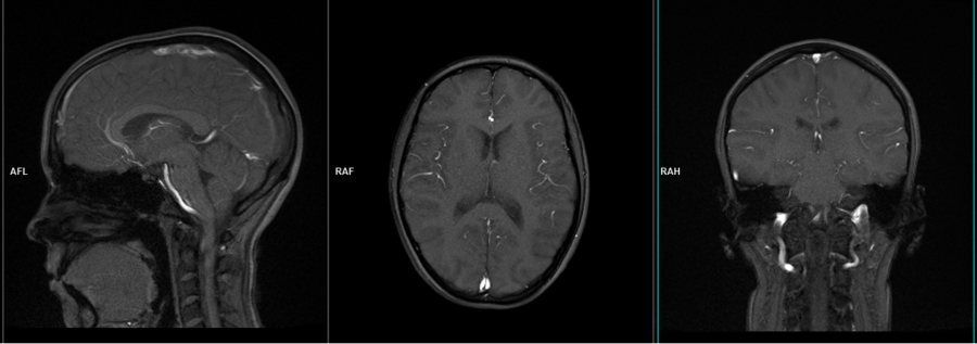
MRI cisternography is a specialized imaging technique used to visualize cerebrospinal fluid (CSF) pathways and spaces within the brain and spinal cord. It is particularly valuable in diagnosing conditions like CSF rhinorrhea, where there is a leak of CSF from the intracranial space into the nasal cavity.
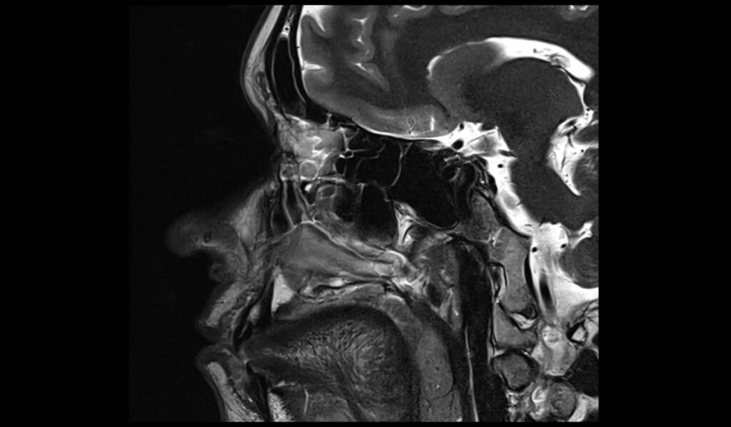
MRI Cisternography 3D SPACE Images
indications for MRI cisternography
- Headache, which may worsen when sitting up and improve when lying down.
- Clear, watery nasal discharge, often one-sided.
- Metallic or salty taste in the mouth.
- Hearing loss or a sense of fullness in the ear.
- Recurrent meningitis.
- CSF Rhinorrhea
Contraindications
- Any electrically, magnetically or mechanically activated implant (e.g. cardiac pacemaker, insulin pump biostimulator, neurostimulator, cochlear implant, and hearing aids)
- Intracranial aneurysm clips (unless made of titanium)
- Pregnancy (risk vs benefit ratio to be assessed)
- Ferromagnetic surgical clips or staples
- Metallic foreign body in the eye
- Metal shrapnel or bullet
Patient preparation for MRI cisternography
- A satisfactory written consent form must be taken from the patient before entering the scanner room
- Ask the patient to remove all metal objects including keys, coins, wallet, cards with magnetic strips, jewellery, hearing aid and hairpins
- Ask the patient to undress and change into a hospital gown
- Request the patient to use the rest room before procedure
- Gadolinium should only be given to the patient if GFR is > 30
- Contrast injection risk and benefits must be explained to the patient before the scan
- Claustrophobic patients may be accompanied into the scanner room e.g. by staff member or relative with proper safety screening
- Offer headphones and earplugs for communicating with the patient and for ear protection.
- Explain the procedure to the patient and answer questions
- Note the hight and weight of the patient
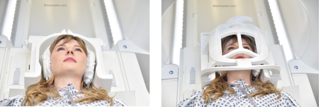
Positioning for CSF Flow MRI
- Head first supine
- Position the head in the head coil and immobilise with cushions
- Give cushions under the legs for extra comfort
- Now, connect the top portion of the head coil and secure it in place.
- Centre the laser beam localiser over the glabella
Recommended MRI cisternography Protocols and Planning
Localiser
A three-plane localizer must be taken at the beginning to localize and plan the sequences. Localizers are usually less than 25 seconds and are T1-weighted low-resolution scans.
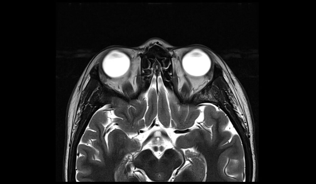
T2 tse axial
Plan the axial slices on the sagittal plane and position the block parallel to the genu and splenium of the corpus callosum. Verify the planning block in the other two planes and ensure that an appropriate angle is maintained in the coronal plane, making it perpendicular to the line of the midline of the brain and the 4th ventricle. Ensure that the number of slices is sufficient to cover the entire brain from the vertex to the line of the foramen magnum.

Protocol Parameters of T2
TR 4000-5500 | TE 100-120 | SLICE 3MM | FLIP 130-150 | PHASE R>L | MATRIX 320X320 | FOV 210-230 | GAP 10% | NEX(AVRAGE) 2 |
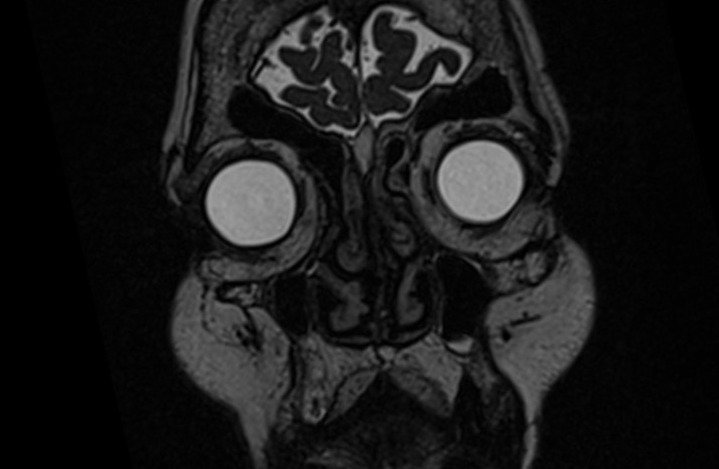
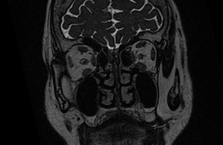
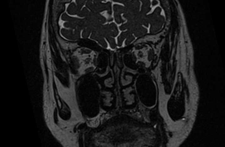
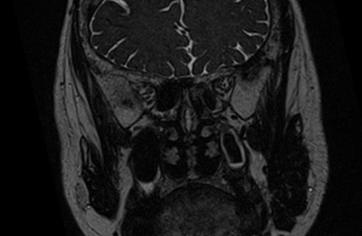
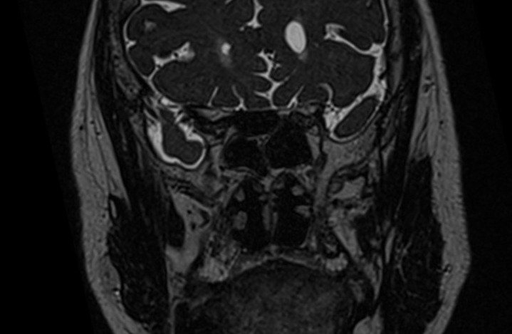
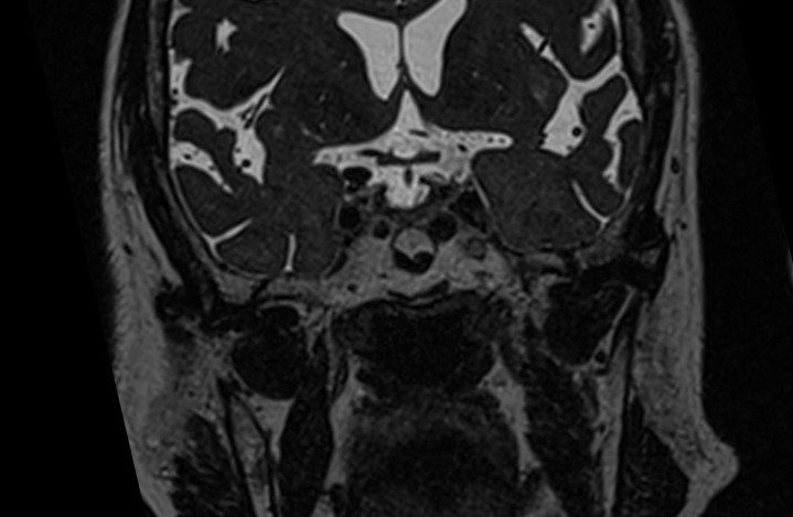
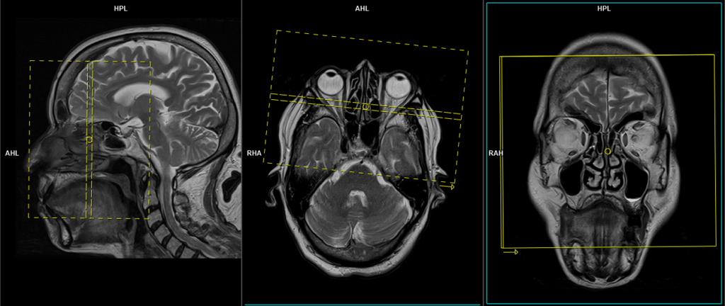
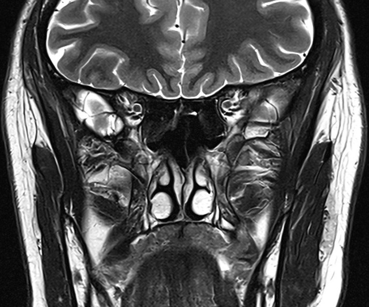
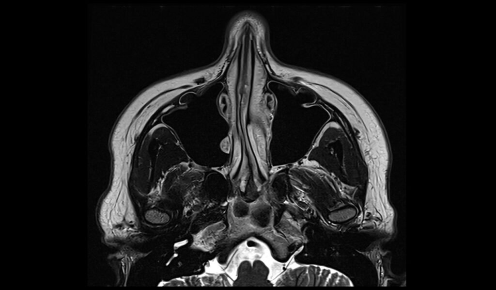
T2 SPACE 3D small FOV coronal, 0.5 mm isotropic, with high TE.
Plan the coronal slices on the sagittal plane; angle the planning block perpendicular to the hard palate. Check the positioning block in the other two planes. An appropriate angle must be given in the axial plane (perpendicular to the nasal septum). Slices must be sufficient to cover the sinus area from the nose vestibule to the brain stem.

Protocol Parameters of T2 SPACE 3D
TR 4000-6000 | TE 200-300 | SLICE .5mm | FLIP 80 | PHASE R>L | MATRIX 256X256 | FOV 160-170 | GAP 20% | NEX(AVRAGE) 1 |
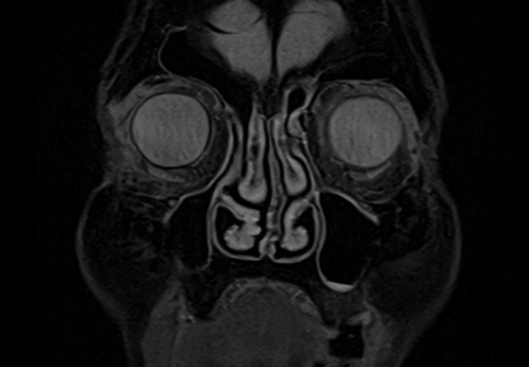
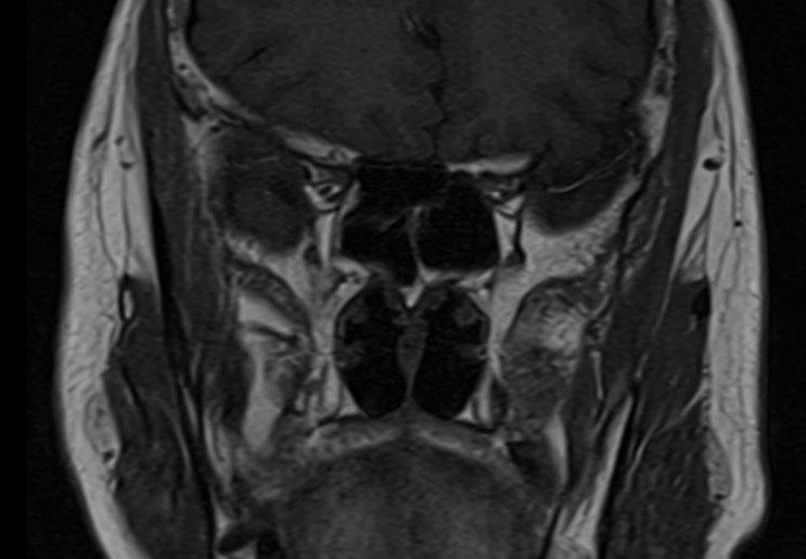
T2 STIR coronal 2mm small FOV
Plan the coronal slices on the sagittal plane; angle the planning block perpendicular to the hard palate. Check the positioning block in the other two planes. An appropriate angle must be given in the axial plane (perpendicular to the nasal septum). Slices must be sufficient to cover the entire sinuses from the tip of the nose to the brain stem.
Parameters
TR 5000-6000 | TE 110 | FLIP 150 | NEX 4 | SLICE 2 MM | MATRIX 240X240 | FOV 160-170 | PHASE R>L | GAP 10% | TI 150 |

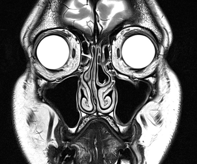
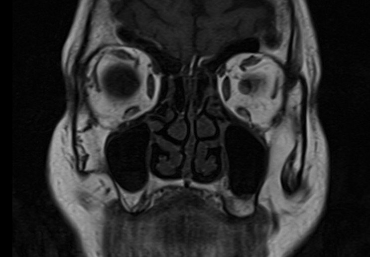
T2 TSE coronal 2mm small FOV
Plan the coronal slices on the sagittal plane; angle the planning block perpendicular to the hard palate. Check the positioning block in the other two planes. An appropriate angle must be given in the axial plane (perpendicular to the nasal septum). Slices must be sufficient to cover the entire sinuses from the tip of the nose to the brain stem.
Parameters
TR 4000-5000 | TE 100-120 | SLICE 2MM | FLIP 130-150 | PHASE R>L | MATRIX 256X256 | FOV 150-170 | GAP 10% | NEX(AVRAGE) 2 |

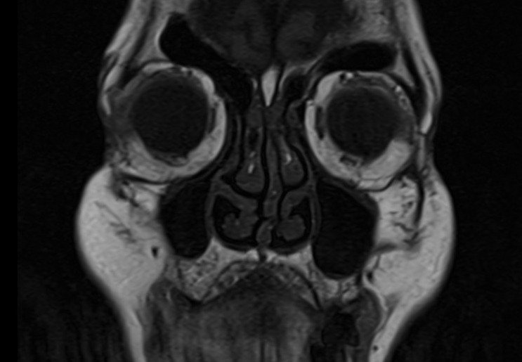
T1 tse coronal 2 mm small FOV
Plan the coronal slices on the sagittal plane; angle the planning block perpendicular to the hard palate. Check the planning block in the other two planes. An appropriate angle must be given in the axial plane (perpendicular to the nasal septum). Slices must be sufficient to cover the entire sinuses from the tip of the nose to the brain stem.
Parameters
TR 450-650 | TE 15-25 | SLICE 2 MM | FLIP 140 | PHASE R>L | MATRIX 256X256 | FOV 160-170 | GAP 10% | NEX(AVRAGE) 3 |
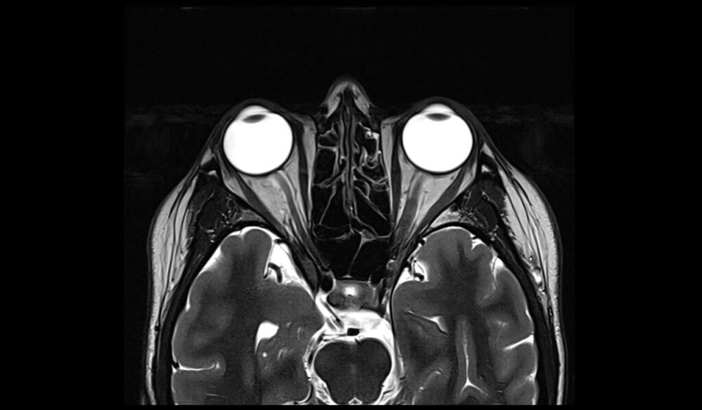
T2 TSE axial 2mm SFOV
Plan the axial slices on the sagittal plane and angle the planning block parallel to the hard palate. Check the planning block in the other two planes. An appropriate angle must be given in the coronal plane (perpendicular to the nasal septum). The slices must be sufficient to cover the entire sinuses, from the superior border of the frontal sinus down to the level of the upper lip.

Parameters
TR 4000-5000 | TE 100-120 | SLICE 2MM | FLIP 130-150 | PHASE R>L | MATRIX 256X256 | FOV 150-170 | GAP 10% | NEX(AVRAGE) 2 |
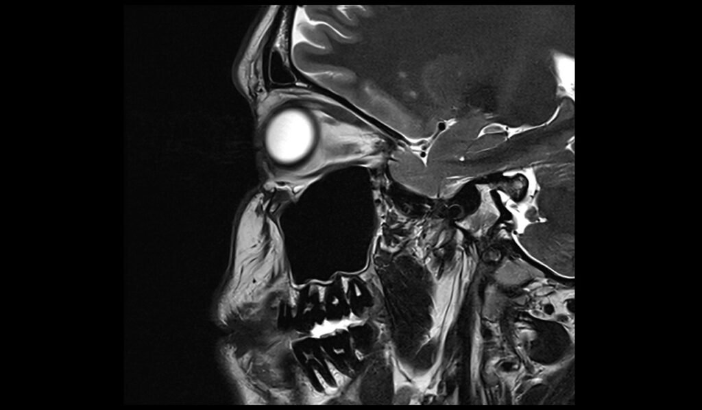
T2 tse sagittal 2mm SFOV
Plan the sagittal slices on the axial plane; angle the planning block parallel to the nasal septum. Check the planning block in the other two planes. An appropriate angle must be given in the coronal plane (parallel to the nasal septum). Slices must be sufficient to cover the entire sinuses from right to left.

Parameters
TR 4000-5000 | TE 100-120 | SLICE 2MM | FLIP 130-150 | PHASE A>P | MATRIX 256X256 | FOV 150-170 | GAP 10% | NEX(AVRAGE) 2 |

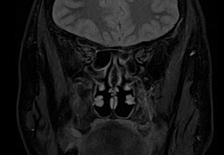
For contrast enhancement scans
Use T1-weighted sequences (T1 tse DIXON) in both axial and coronal planes after the administration of IV gadolinium DTPA injection (copy the planning outlined above). The document below provides access to the recommended dosage of gadolinium DTPA injection as advised by the manufacturer.