CSF Flow Chiari I Malformation MRI: Protocol and planning
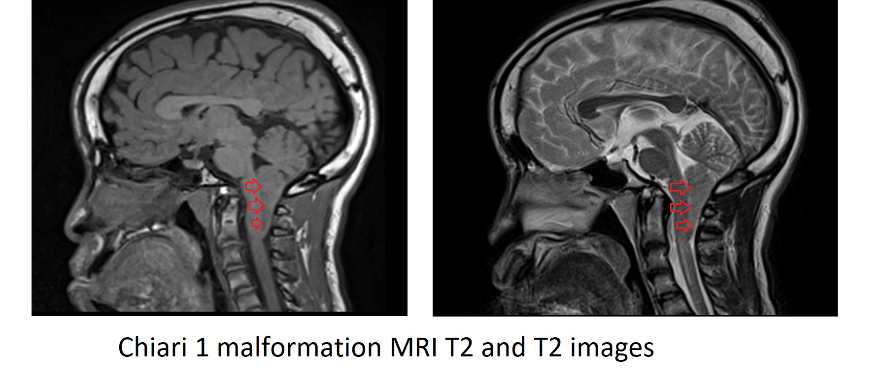
Chiari I Malformation
Chiari I malformation is a structural defect in the brain where the cerebellar tonsils, located at the lower part of the cerebellum, extend into the foramen magnum (the opening at the base of the skull). This displacement can disrupt the normal flow of cerebrospinal fluid (CSF) and compress the brainstem and spinal cord. Chiari I malformation is typically congenital, meaning it is present at birth, but symptoms may not appear until adolescence or adulthood.
indications for Cerebrospinal fluid (CSF) flow MRI
- Chiari I Malformation
Contraindications
- Any electrically, magnetically or mechanically activated implant (e.g. cardiac pacemaker, insulin pump biostimulator, neurostimulator, cochlear implant, and hearing aids)
- Intracranial aneurysm clips (unless made of titanium)
- Pregnancy (risk vs benefit ratio to be assessed)
- Ferromagnetic surgical clips or staples
- Metallic foreign body in the eye
- Metal shrapnel or bullet
Patient preparation for CSF flow MRI
- A satisfactory written consent form must be taken from the patient before entering the scanner room
- Ask the patient to remove all metal objects including keys, coins, wallet, cards with magnetic strips, jewellery, hearing aid and hairpins
- Ask the patient to undress and change into a hospital gown
- Request the patient to use the rest room before procedure
- Follow the appropriate manufacturer's instructions for the pulse oximeter and its Bluetooth receiver placement.
- Claustrophobic patients may be accompanied into the scanner room e.g. by staff member or relative with proper safety screening
- Offer headphones and earplugs for communicating with the patient and for ear protection.
- Explain the procedure to the patient and answer questions
- Note the hight and weight of the patient
Positioning
- Head first supine
- Position the head in the head and neck coil and immobilise with cushions
- Give cushions under the legs for extra comfort
- Centre the laser beam localiser over the mid neck (2.5cm below the chin in chin-down position)

Pulse gating technique
Cerebrospinal fluid (CSF) flow imaging is performed using pulse gating techniques to synchronize the imaging with the cardiac cycle. This synchronization is crucial because the flow of CSF is influenced by the cardiac pulse, which causes periodic fluctuations in the pressure gradients across the central nervous system. As the heart beats, it not only pumps blood but also subtly affects the movement of CSF, making its dynamics inherently pulsatile.
Pulse gating in CSF flow imaging typically involves the use of electrocardiogram (ECG) or peripheral pulse gating to capture the precise phases of the cardiac cycle. By coordinating the MRI scans with these phases, it becomes possible to obtain highly detailed and dynamic images of CSF flow. This method allows for the measurement of CSF velocity and flow patterns at different times within the cardiac cycle, providing a comprehensive view of its temporal and spatial variations.

Recommended CSF Flow Chiari I Malformation Protocol and Planning
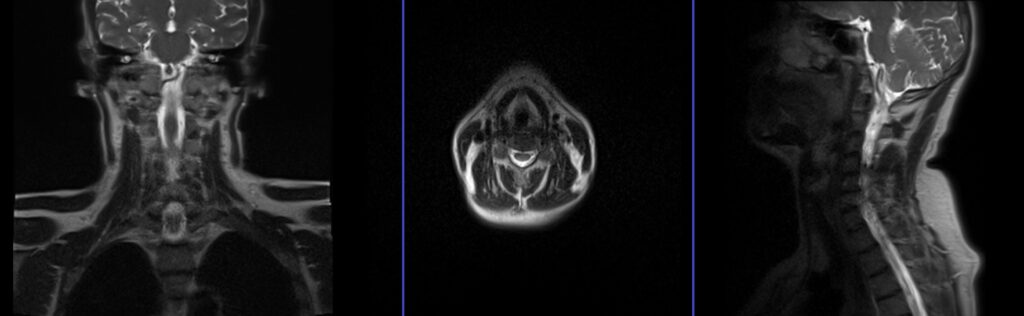
localiser
A three-plane localizer must be taken at the beginning to localize and plan the sequences. Localizers are normally less than 25 seconds, and they consist of T2\T1 weighted low-resolution scans.
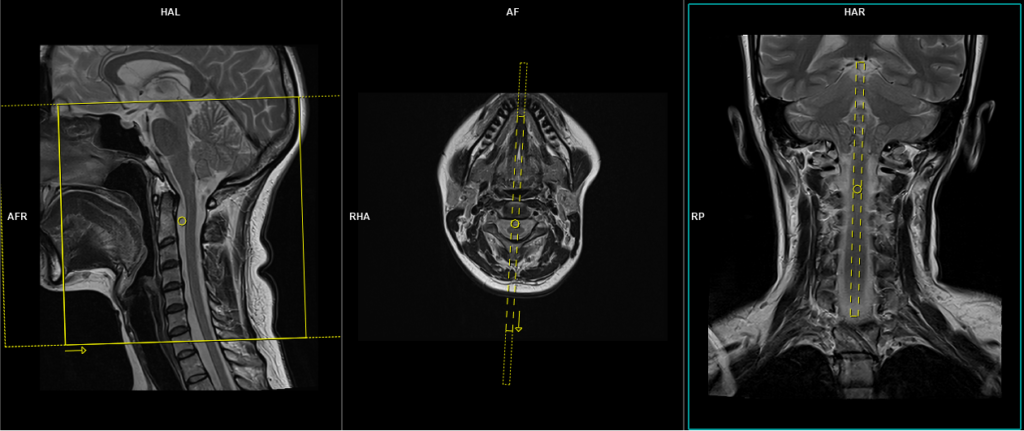
T2 SPACE 3D sagittal 0.7 mm isotropic
Plan the sagittal 3D block on the coronal localizer, angle the positioning block parallel to the spinal cord. Verify the positioning block in the other two planes. In the axial plane, ensure the block is angled appropriately, parallel to the line running through the center of the vertebral body along the length of the spinous process. Check the positioning block in the sagittal plane to ensure the field of view (FOV) is large enough to cover the cerebellum and upper cervical spine, from the pituitary stalk down to C6 (typically 200 mm). The slices should sufficiently cover the spine from the lateral border of the right transverse process to the lateral border of the left transverse process. Place a saturation band over the neck (in front of the esophagus) in the sagittal plane to avoid swallowing and pulsation artifacts over the spinal area. The phase direction should be head to foot to prevent motion artifacts from the neck.

Parameters
TR 1500-2000 | TE 130-160 | SLICE 0.7 MM | FLIP 120-150 | PHASE H>F | MATRIX 256X256 | FOV 200-250 | GAP 20% | NEX(AVRAGE) 1.4 |
3D SPACE sagittal Images
CSF flow and VENC settings
Normal CSF flow velocities can vary significantly based on the individual, the location measured, and physiological conditions, but general guidelines include:
- Peak systolic velocities range from 5 to 10 cm/s in the cerebral aqueduct.
- VENC settings are often set around 5 to 25 cm/s, depending on the expected velocity of CSF flow in the region of interest.
The ideal method for conducting a CSF flow sequence involves using a VENC scout to identify the optimal flow value. However, radiographers often find it challenging to determine this optimal value. For this reason, we prefer to perform multiple scans with different VENC settings. Since the scan time is very short per sequence, performing multiple VENC scans takes almost the same amount of time as performing the scans with a VENC scout.
CSF Flow Chiari I Malformation in-plane scan protocol and planning
CSF flow in-plane VENC 6cm\sec
Plan the sagittal flow sequence slice on the coronal localizer, angle the positioning block parallel to the mid spinal cord. Verify the positioning block in the other two planes. In the axial plane, ensure the block is appropriately angled, parallel to the line running through the center of the vertebral body along the length of the spinous process. Check the positioning block in the sagittal plane to ensure the field of view (FOV) is large enough to cover the cerebellum and upper cervical spine, from the pituitary stalk down to C6 (typically 200 mm).
Parameters
TR 23.7 | TE 7.78 | FLIP 20 | NEX 1 | SLICE 6MM | MATRIX 256×205 | FOV 180 | PHASE A>P | VELOCITY 6cm\sec | TRIGGER Pulse/Retro |
CSF flow in-plane images
Re-phased Image

Magnitude Image

Phase Image


Repeat the in-plane sagittal PC flow sequence with VENC 10 cm/sec, 15 cm/sec, and 20 cm/sec
CSF flow through- plane scan protocol and planning
CSF flowthrough- plane VENC 6cm\sec
Plan the axial CSF flow slice on the sagittal plane just below the foramen magnum and angle the positioning block perpendicular to the spinal cord. In the coronal plane, ensure the block is also angled appropriately, perpendicular to the spinal cord.

Parameters
TR 23.7 | TE 7.78 | FLIP 20 | NEX 1 | SLICE 6MM | MATRIX 256×205 | FOV 180 | PHASE A>P | VELOCITY 6cm\sec | TRIGGER Pulse/Retro |
Re-phased Image

Magnitude Image

Phase Image


The post-processing of the study is performed by the radiologist at the workstation. Each manufacturer has its own post-processing software. However, if anyone is interested in learning more about this, please refer to the manufacturer’s scanner manual.