Cardiac MRI Flow Quantification( Pulmonary and Aortic Flow)
Flow quantification MRI
Phase-contrast magnetic resonance imaging is a non-invasive MRI technique used for the quantitative analysis of blood flow. This technique employs velocity-induced phase shifts to distinguish moving protons in flowing blood from stationary protons in surrounding tissues. Protons moving in the direction of the magnetic field experience a phase shift, which is calculated using two opposing gradient pulses known as velocity-encoding gradients.
Phase-contrast imaging generates magnitude and phase cine images. Magnitude images contain signal amplitude information, while phase images convey flow and velocity data. Magnitude images resemble bright blood cine images and are used for anatomic orientation.
Phase images are displayed in grayscale. Stationary protons in tissues like fat, muscles, and bones appear uniformly grey. Moving blood protons traveling in the velocity-encoding direction appear white, while those flowing in the opposite direction appear black. Tissues like lungs, with random phase information, display as white and black pixels. Phase images are vital for flow and velocity measurements.
Phase-contrast imaging can be performed in-plane and through-plane. Through-plane imaging is perpendicular to the flow direction, used for velocity measurement and flow quantification. In-plane flow imaging is parallel to the flow direction, offering full visualization of flow jets and peak flow velocity estimation.
Accurate flow measurements require appropriate planning. Flow measurements are most precise when the imaging plane is perpendicular to the flow (through-plane imaging). Failure to achieve true perpendicular alignment can lead to inaccurate flow measurements.

Indications for cardiac MRI Flow Quantification
- Aortic valvular disease (AVD)
- aortic stenosis
- Pulmonary valve stenosis
- pulmonary valve defect
- Pulmonary arterial hypertension (PAH)
Contraindications
- Any electrically, magnetically or mechanically activated implant (e.g. cardiac pacemaker, insulin pump biostimulator, neurostimulator, cochlear implant, and hearing aids)
- Intracranial aneurysm clips (unless made of titanium)
- Pregnancy (risk vs benefit ratio to be assessed)
- Ferromagnetic surgical clips or staples
- Metallic foreign body in the eye
- Metal shrapnel or bullet
Patient preparation for cardiac MRI
- A satisfactory written consent form must be taken from the patient before entering the scanner room
- Ask the patient to remove all metal objects including keys, coins, wallet, cards with magnetic strips, jewellery, hearing aid and hairpins
- Ask the patient to undress and change into a hospital gown
- Instruct the patient to hold their breath for the breath hold scans and breathe gently for the gated scans (its advisable to coach the patient two to three times before starting the scan)
- Request the patient to use the rest room before procedure
- Follow the appropriate manufacturer’s instructions for the ECG electrodes and the blue tooth receiver placement
- If the chest is covered with hair it is necessary to shave the required area before placing the ECG electrodes
- Thoroughly clean the ECG contact area with an abrasive gel
- Claustrophobic patients may be accompanied into the scanner room e.g. by staff member or relative with proper safety screening
- Offer headphones for communicating with the patient and ear protection
- Explain the procedure to the patient and answer questions
- Note the weight of the patient
Positioning for Cardiac MRI
- Position the patient in a supine position with head pointing towards the magnet (head first supine)
- Position the patient over the spine coil and connect the ECG electrodes as specified above and in accordance with the specific manufacturer’s instructions
- Check the quality of the ECG in the integrated ECG display on the scanner terminal. If the signal is not satisfactory and consistent, change the location of the electrodes
- Place the body coil or the dedicated cardiac coil over the chest
- Securely tighten the coil using straps to prevent respiratory artefacts
- Give cushions under the head and legs for extra comfort
- Centre the laser beam localiser over mid chest (i.e. over the nipples)
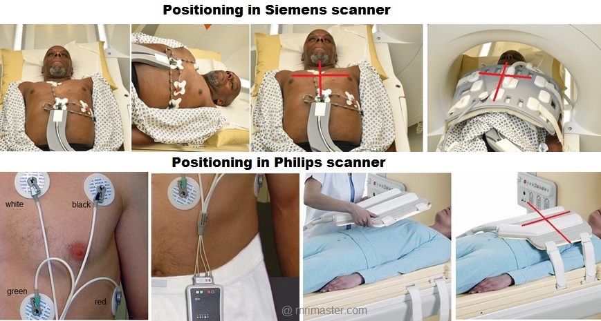
Aortic Flow Quantification
Recommended Aortic Flow Quantification Protocols and Planning
Localiser
An initial three-plane SSFP (TrueFISP, B-FFE, or FIESTA) localizer scan is required for localization and sequence planning. These fast single-shot localizers have an acquisition time of under 25 seconds, making them excellent for localizing chest structures.
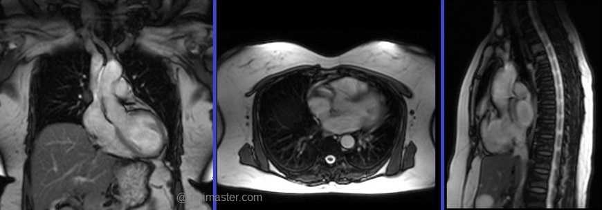
Cardiac MRI planning localiser
Plan the axial localizer on the coronal plane and position the block across the chest as shown. The slices must cover the entire heart from the aortic arch to the diaphragm (usually 3-4 slices). Check the position in the other two planes.
Plan the sagittal localizer on the coronal plane and position the block parallel to the chest as demonstrated. The slices should encompass the entire heart from right to left (usually 3-4 slices). Verify the position in the other two planes.
Plan the coronal localizer on the axial plane and position the block across the chest as indicated. The slices must encompass the entire heart from the sternum to the thoracic aorta (usually 3-4 slices). Confirm the position in the other two planes.
All three blocks must be ISO-centered within the magnetic bore to avoid any inhomogeneity artifacts. These localizers are performed using a combination of ECG gating and breath-holding. Scans should be conducted during an expiratory breath-hold with an ECG trigger for every heartbeat (In our department, we instruct patients to take two breaths in and out before giving the “breathe out and hold” instruction).

T2 TRUE FISP Bight blood axial
Plan the axial T2 scans on the coronal localizer. Plan the planning block straight across the chest, as shown. Verify the positioning in the other two planes. An appropriate angle must be established in the sagittal plane (perpendicular to the thoracic spine). The number of slices should be sufficient to cover the heart from the aortic arch to the apex (usually 18-20 slices). These axial slices are acquired using a combination of ECG gating and breath-holds. Scans should be performed under expiratory breath-holds, with ECG triggers set for every second heartbeat. Axial bright blood scans involve a multiple breath-hold technique that acquires 8-10 slices with each breath hold. In our department, the cardiologist prefers conducting bright blood axials.

Recommended Protocol
TR 278 | TE 1.14 | FLIP 80 | NEX 1 | SLICE 8MM | MATRIX 224×224 | FOV 360 | PHASE A>P | OS NO | TRIGGER YES |
Two chamber localiser
Plan the 2-chamber localizer on the axial plane and angle the planning block parallel to the interventricular septum. Move the position block to the center of the left ventricle, aligning it with the line along the center of the mitral valve and left ventricular apex. (Note: In most patients, these structures may not be visible in the same image; scroll through the axial images to identify both structures.) Verify the position in the other two planes. Provide an appropriate angle in the sagittal plane to maintain parallel alignment with the interventricular septum. This single-slice (non-cine) 2-chamber localizer is performed using a combination of ECG gating and breath-holding. Scans should be conducted during expiration breath-holds with an ECG trigger set for every heartbeat.

Short axis localiser
Plan the short-axis localizer using the 2-chamber view as a reference, and orient the planning block perpendicular to the line running along the center of the mitral valve and the left ventricular apex, essentially perpendicular to the long axis of the left ventricle. Confirm the positioning in the other two planes as well. Provide an appropriate angle for the axial plane, which is perpendicular to the interventricular septum. Acquire slices that adequately cover the heart from the middle of the left atrium to the left ventricular apex; typically, 8-10 slices are needed. This multi-slice, non-cine short-axis localizer is conducted using a combination of ECG gating and breath-holding. Perform scans during expiration with breath-holding, triggering the ECG with each heartbeat.

Three chamber (Left Ventricular Outflow Tract LVOT)cine
Plan the 3-chamber cine on the short-axis localizer and angle the planning block parallel to the line along the center of the aortic valve and the left ventricle (i.e., perpendicular to the posterolateral left ventricle wall). Check the position in the other two planes. An appropriate angle must be given in the 2-chamber localizer (parallel to the line along the center of the mitral valve and the left ventricular apex). This retrospective 3-chamber cine scan is performed with a combination of ECG gating and breath-hold. Scans should be conducted under expiration breath-hold.
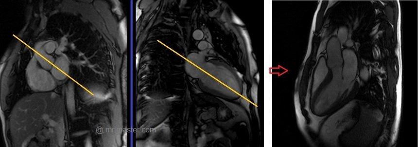
Recommended Protocol
TR 33 | TE 1.3 | FLIP 57 | NEX 1 | SLICE 7MM | MATRIX 176×167 | FOV 300 | PHASE A>P | OS 10% | TRIGGER YES |
Left Ventricular Outflow Tract coronal cine
Plan the Left Ventricular Outflow Tract coronal cine using the 3-chamber cine images. Angle the planning block parallel to the line along the center of the aortic valve and ascending aorta. The LVOT coronal scan is usually planned only in the 3-chamber view. If the manufacturer has a ‘perpendicular’ function in the planning tab, please use it to achieve more accurate planning. This retrospective Left Ventricular Outflow Tract coronal cine scan is performed using a combination of ECG gating and breath-holds. Scans should be conducted under expiration breath-hold
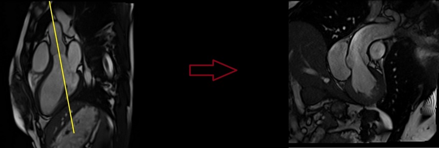
Recommended Protocol
TR 33 | TE 1.3 | FLIP 57 | NEX 1 | SLICE 7MM | MATRIX 176×167 | FOV 300 | PHASE R>L | OS 10% | TRIGGER YES |
Aortic through plane flow protocol and planning
Flow velocity encoding scout (VENC scout)
A flow velocity encoding scout is utilized to identify the most accurate flow velocities. Velocity scouting (VENC scout) involves multiple flow velocities ranging from 50 to 200. This scout is then employed to pinpoint the most accurate flow velocity, where the ascending aorta appears bright, and the descending aorta appears dark. Based on the velocity encoding map images, the user must select the velocity at which the ascending aorta is very bright without any velocity aliasing artifacts (as shown in the picture below). This velocity value is subsequently applied for aortic through-plane flow imaging.
Velocity aliasing artifacts: These artifacts occur when the peak velocity of the flowing blood being imaged exceeds the encoding velocity or VENC.

Flow velocity encoding scout planning
Plan the velocity encoding scout axial on the 3-chamber cine images. Angle the planning block perpendicular to the ascending aorta, right above the sinotubular junction. Check the position in the Left Ventricular Outflow Tract coronal cine. An appropriate angle must be given in the Left Ventricular Outflow Tract coronal cine (perpendicular to the ascending aorta). Phase-contrast axial scans are performed with a combination of ECG gating and breath-hold. Scans should be performed under expiration breath-hold.

Recommended Protocol
TR 46.7 | TE 2.48 | FLIP 20 | NEX 1 | SLICE 6MM | MATRIX 192×192 | FOV 360 | PHASE A>P | VELOCITY 50cm\sec 100cm\sec 130cm\sec 160cm\sec 190cm\sec | TRIGGER YES |
Aorta through plane flow planning
Plan the Phase-contrast axial scans on the 3-chamber cine images. Angle the positioning block perpendicular to the ascending aorta, just above the sinotubular junction. Verify the position in the Left Ventricular Outflow Tract coronal cine. Ensure that an appropriate angle is maintained in the Left Ventricular Outflow Tract coronal cine, which should be perpendicular to the ascending aorta.
Phase-contrast axial scans should be performed using a combination of ECG gating and breath-holding techniques. Perform the scans during expiration breath-hold, using the most suitable velocity value obtained from the Venc scout.

Recommended Protocol
TR 42.3 | TE 3.1 | FLIP 20 | NEX 1 | SLICE 6MM | MATRIX 208×192 | FOV 360 | PHASE A>P | VELOCITY 160cm\sec | TRIGGER YES |
Aorta in plane flow planning (candy cane view).
Plan the phase-contrast sagittal scan on the bright blood axial images. Align the position block parallel to the line bisecting the ascending aorta, aortic arch, and descending aorta. Verify the position in the coronal localizer. Ensure that an appropriate angle is set in the coronal localizer, parallel to the descending aorta. Phase-contrast sagittal scans should be conducted using a combination of ECG gating and breath-holding. Perform scans under expiration breath-holding with the optimal velocity value obtained from the Venc scout.

Recommended Protocol
TR 42.3 | TE 3.1 | FLIP 20 | NEX 1 | SLICE 6MM | MATRIX 208×208 | FOV 360 | PHASE A>P | VELOCITY 160cm\sec | TRIGGER YES |
Aorta in plane flow planning 3-point planning
3-point planning is a software option made available by certain manufacturers. It uses three different points in curved anatomy to achieve more accurate planning. The planning block will automatically align parallel to the differentiated points.
To plan the phase-contrast aorta in plane flow on the axial bright blood images, use the 3-point planner. Set the first point in the ascending aorta, the second point in the mid-aortic arch, and the third point at the descending aorta. The planning block will automatically align parallel to the aorta.
Phase-contrast sagittal scans are performed using a combination of ECG gating and breath-hold. Scans should be conducted under expiration breath-hold with the most appropriate velocity value from the Venc scout.
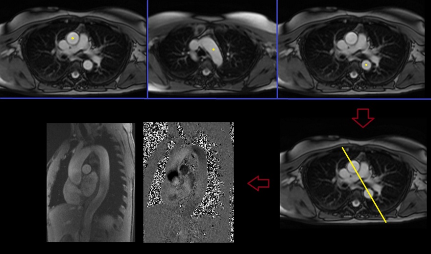
Recommended Protocol
Pulmonary Artery Flow Quantification
Main pulmonary trunk Flow
Right Ventricular Outflow Tract cine 3-point planning
Three-point planning is a software option made available by certain manufacturers. Three-point planning employs three distinct points in curved anatomy to achieve more accurate planning. The planning block will automatically align parallel to the designated points. Plan the cine for the Right Ventricular Outflow Tract on the axial bright blood images. Utilize the 3-point planner to establish the first point in the right atrium, the second point in the mid pulmonary trunk, and the third point at the pulmonary artery bifurcation. The planning block will then automatically align parallel to the right ventricular outflow tract. This retrospective coronal cine scan of the Right Ventricular Outflow Tract is performed with a combination of ECG gating and breath-hold. Scans should be conducted while maintaining an expiration breath-hold.

Recommended Protocol
TR 33 | TE 1.3 | FLIP 57 | NEX 1 | SLICE 7MM | MATRIX 176×167 | FOV 300 | PHASE A>P | OS 10% | TRIGGER YES |
Pulmonary trunk through plane flow planning
Plan the phase-contrast axial imaging of the right ventricular outflow tract (RVOT) cine images. Angle the positioning block perpendicular to the pulmonary trunk, just above the pulmonary valve. Verify the positioning in the axial bright blood images. Ensure that the angle is appropriate in the axial bright blood images, making it perpendicular to the pulmonary trunk. Phase-contrast axial scans are to be performed using a combination of ECG gating and breath-holding. Perform scans while the patient is holding their breath during expiration, using the most appropriate velocity value obtained from the Venc scout.
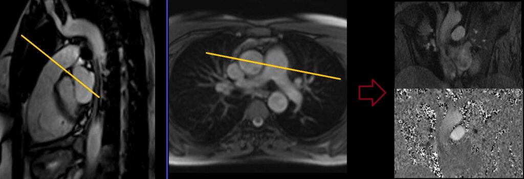
Recommended Protocol
TR 42.3 | TE 3.1 | FLIP 20 | NEX 1 | SLICE 6MM | MATRIX 208×192 | FOV 360 | PHASE R>L | VELOCITY 160cm\sec | TRIGGER YES |
Pulmonary trunk through plane flow planning
Plan the phase-contrast axial imaging of the right ventricular outflow tract (RVOT) cine images. Angle the positioning block perpendicular to the pulmonary trunk, just above the pulmonary valve. Verify the positioning in the axial bright blood images. Ensure that the angle is appropriate in the axial bright blood images, making it perpendicular to the pulmonary trunk. Phase-contrast axial scans are to be performed using a combination of ECG gating and breath-holding. Perform scans while the patient is holding their breath during expiration, using the most appropriate velocity value obtained from the Venc scout.

Recommended Protocol
TR 42.3 | TE 3.1 | FLIP 20 | NEX 1 | SLICE 6MM | MATRIX 208×192 | FOV 360 | PHASE R>L | VELOCITY 160cm\sec | TRIGGER YES |
Right Pulmonary artery through plane flow planning
Right Pulmonary artery coronal localizer
The RT Pulmonary artery coronal localizer is utilized to accurately plan the RT Pulmonary artery through-plane flow imaging.
To plan the coronal localizer, refer to the axial bright blood images and align the position block parallel to the right pulmonary artery. If the scanner features a perpendicular function, use it to automatically align the slices in the other planes. If this function is unavailable, proceed with planning based on the axial bright blood images alone.
T2 coronal localizer scans are performed using a combination of ECG gating and breath-holding techniques. Ensure that scans are conducted during expiration breath-hold, selecting the most appropriate velocity value from the Venc scout.
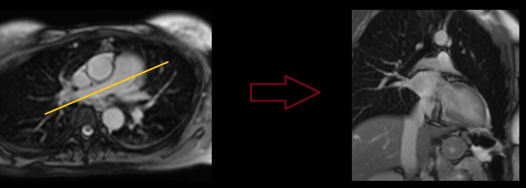
Right Pulmonary artery through plane flow
Plan the Phase-contrast axial scans for the axial bright blood images. Position the blocking device perpendicular to the mid-right pulmonary artery. Verify the positioning using the coronal right pulmonary artery localizer. Ensure that the angle is appropriate, perpendicular to the right pulmonary artery. Perform Phase-contrast axial scans using a combination of ECG gating and breath-holding techniques. Execute the scans during expiration breath-holding, selecting the most suitable velocity value from the Venc scout.

Recommended Protocol
TR 42.3 | TE 3.1 | FLIP 20 | NEX 1 | SLICE 6MM | MATRIX 208×192 | FOV 360 | PHASE A>P | VELOCITY 160cm\sec | TRIGGER YES |
Left Pulmonary artery through plane flow planning
Left Pulmonary artery coronal localizer
The LT Pulmonary artery coronal localizer is employed for precise planning of the left pulmonary artery via flow imaging in the coronal plane.
To set up the coronal localizer, begin with the axial bright blood images. Position the block parallel to the left pulmonary artery. If the scanner offers a perpendicular function, utilize it to automatically align the slices in the other planes. If this function is unavailable, proceed with planning in the axial plane only.
T2 coronal localizer scans are conducted using a combination of ECG gating and breath-holding techniques. Perform scans during expiration breath-holding and select the most appropriate velocity value from the Venc scout.
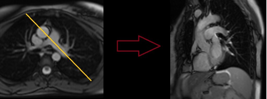
Left Pulmonary artery through plane flow
Plan the Phase-contrast axial scans for the axial bright blood images. Align the position block perpendicular to the mid-left pulmonary artery. Verify the positioning using the coronal left pulmonary artery localizer. Ensure an appropriate angle is set in the coronal left pulmonary artery localizer (perpendicular to the left pulmonary artery). Phase-contrast axial scans should be conducted using a combination of ECG gating and breath-holding. Perform the scans during an expiratory breath-hold, using the most suitable velocity value determined from the Venc scout.
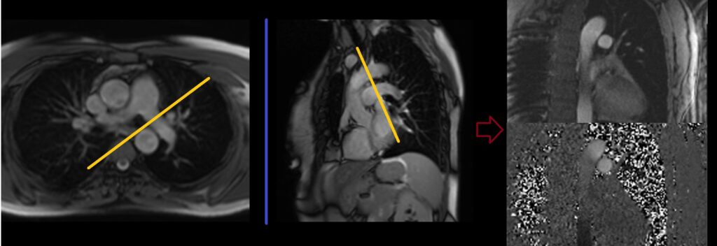
Recommended Protocol
TR 42.3 | TE 3.1 | FLIP 20 | NEX 1 | SLICE 6MM | MATRIX 208×192 | FOV 360 | PHASE A>P | VELOCITY 160cm\sec | TRIGGER YES |
Pulmonary Vein Flow Quantification
Right Pulmonary Vein through plane flow planning
right Pulmonary vein coronal localizer
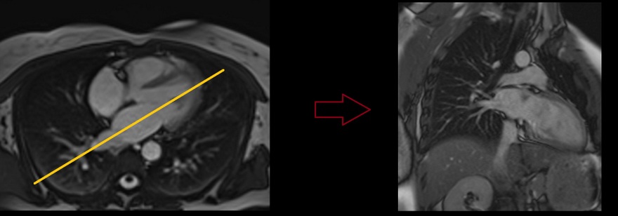
The RT Pulmonary vein coronal localizer is used for accurate planning of the RT Pulmonary artery through-plane flow imaging. Plan the coronal localizer on the axial bright blood images. Angle the positioning block parallel to the right pulmonary vein. If the scanner has a perpendicular function, use it to auto-align the slices in the other planes. If the function is not available, use the axial images only. The T2 coronal localizer scans are performed with a combination of ECG gating and breath-hold. Scans should be performed under expiratory breath-hold with the most appropriate velocity value from the Venc scout.
Right Pulmonary vein through plane flow
Plan the Phase-contrast axial scans for the axial bright blood images. Align the positioning block perpendicular to the mid-right pulmonary vein. Verify the positioning in the coronal right pulmonary vein localizer. Ensure an appropriate angle in the coronal right pulmonary vein localizer (perpendicular to the right pulmonary vein). Perform Phase-contrast axial scans using a combination of ECG gating and breath-holding. The scans should be conducted during expiration breath-holding with the optimal velocity value from the Venc scout.

Recommended Protocol
TR 42.3 | TE 3.1 | FLIP 20 | NEX 1 | SLICE 6MM | MATRIX 208×192 | FOV 360 | PHASE A>P | VELOCITY 160cm\sec | TRIGGER YES |
Left Pulmonary Vein through plane flow planning
Left Pulmonary vein coronal localizer
The LT pulmonary vein coronal localizer is utilized for precise planning of the left pulmonary vein through-plane flow imaging.
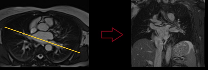
To plan the coronal localizer, start with the axial bright blood images. Position the block parallel to the left pulmonary vein. If the scanner offers a perpendicular function, utilize it to automatically align the slices in other planes. If this function is unavailable, proceed with planning based on the axial images alone. T2 coronal localizer scans are performed using a combination of ECG gating and breath-holding. Ensure that scans are conducted during expiration breath-holding, selecting the most appropriate velocity value from the Venc scout
Left Pulmonary vein through plane flow planning
Plan the Phase-contrast axial scans for the axial bright blood images. Position the blocking device perpendicular to the mid-left pulmonary vein. Verify the positioning using the coronal left pulmonary vein localizer. Ensure the appropriate angle is set in the coronal left pulmonary vein localizer (perpendicular to the left pulmonary vein). Phase-contrast axial scans should be performed using a combination of ECG gating and breath-holding. Conduct the scans during an expiration breath-hold, selecting the most suitable velocity value from the Venc scout.

Recommended Protocol
TR 42.3 | TE 3.1 | FLIP 20 | NEX 1 | SLICE 6MM | MATRIX 208×192 | FOV 360 | PHASE A>P | VELOCITY 160cm\sec | TRIGGER YES |


