MRI SNR vs CNR: Definition, Formula, and Differences Explained
MRI SNR (Signal-to-Noise Ratio)
Signal-to-Noise Ratio (SNR) in MRI is a measure of the clarity of the image, quantifying how much the signal stands out from the background noise. It indicates the strength of the signal relative to the noise level, which affects the overall quality and diagnostic utility of the MRI images.
Formula:
SNR = \(\frac{S}{N}\)
where:
- \(S\) is the mean signal intensity.
- \(N\) is the standard deviation of the noise.
Gauss and Tesla
Gauss and Tesla are units used to measure magnetic field strength, also known as magnetic flux density.
Gauss (G): It is a unit of magnetic flux density in the centimeter-gram-second (CGS) system of units. Named after the German mathematician and physicist Carl Friedrich Gauss, it measures the number of magnetic field lines passing through a square centimeter.
Tesla (T): It is the SI (International System of Units) derived unit of magnetic flux density. Named after Nikola Tesla, a Serbian-American inventor and engineer, it measures the number of magnetic field lines passing through a square meter.
The relationship between these units is that 1 Tesla equals 10,000 Gauss.
The photo displays 5 Gauss lines marked on the floor of a Siemens 3T MRI

The photo displays 5 Gauss lines marked on the floor of a Siemens 1.5T MRI

Importance of the 5 Gauss Line
- Safety for Patients and Staff: Magnetic fields above 5 gauss can affect pacemakers, implanted medical devices, and ferromagnetic objects, posing safety risks.
- Regulatory Compliance: Many health and safety regulations require the demarcation of the 5 gauss line to ensure that only trained personnel with appropriate safety gear enter the high magnetic field area.
Size of the 5 Gauss Line
The 5 Gauss line usually forms an irregular shape around the scanner rather than a perfect circle, influenced by the following:
- Magnet Type and Orientation: The design of the magnet (e.g., superconducting or permanent) and its orientation (horizontal or vertical) can affect how the magnetic field is distributed.
- Building Structure and Materials: Metallic structures within walls or floors can alter the path of the magnetic field, shaping the 5 Gauss line.
- Shielding: Passive or active shielding systems are often employed to contain the magnetic field within the MRI facility, affecting the extent and shape of the 5 Gauss line.
The extent of the 5 gauss line varies depending on the strength of the MRI scanner.
1.5 Tesla Scanners: For a typical 1.5T MRI scanner, the 5 gauss line usually extends about 3-5 meters from the magnet in all directions. This boundary can be larger or smaller based on specific shielding and installation factors.
3 Tesla Scanners: In a 3T scanner, which has a stronger magnetic field, the 5 gauss line generally extends further out, around 4-6 meters from the magnet in all directions.
These distances are approximate and can vary significantly with the design of the magnet, the type of shielding, and the layout of the installation site.
How to Locate the 5 Gauss Line
The 5 gauss line is typically determined during the installation of the MRI scanner and is an important part of the site planning process. Methods to locate this line include:
- Magnetic Field Measurements: Using a gaussmeter, technicians measure the magnetic field intensity around the scanner. The measurements are taken at different points to map the boundary where the field strength drops to 5 gauss.
- Physical Markings: Once determined, the 5 gauss line is often physically marked on the floor or using barriers to clearly indicate the safe boundary for general access.
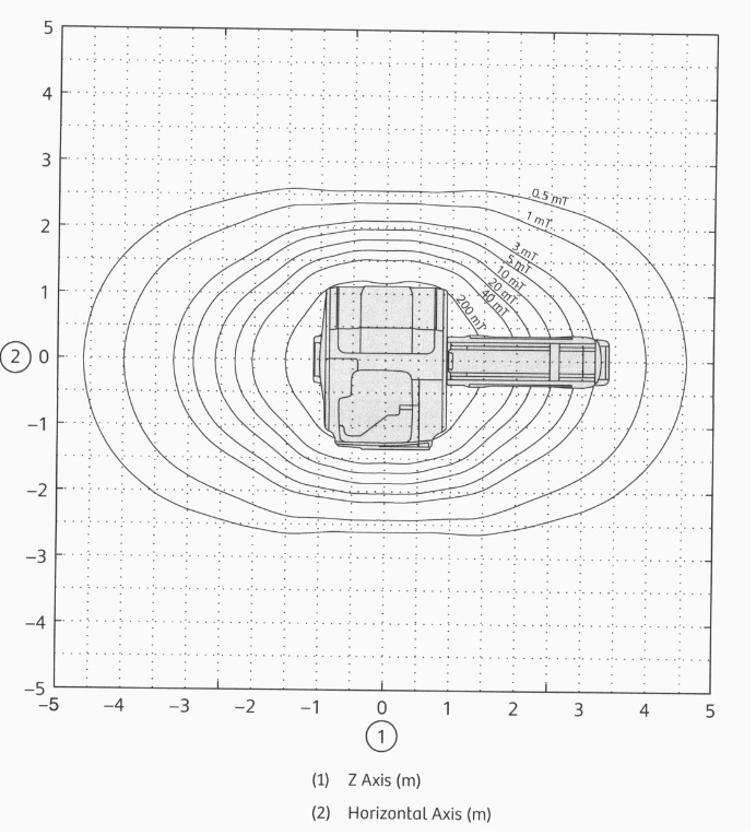
The diagram illustrates the graphical representation of the Gauss line for a Siemens 1.5T MRI system.


